Welding method for CO2 gas shielded welding for super-strength thick steel plate

A technology of gas shielded welding and welding methods, applied in welding equipment, welding/welding/cutting items, arc welding equipment, etc., can solve problems such as improving project construction cycle and cost, increasing welding labor intensity, and increasing process complexity. Achieve the effects of low welding cost, low labor intensity and good impact toughness

Active Publication Date: 2016-06-08
WUHAN UNIV OF SCI & TECH
View PDF2 Cites 5 Cited by
  • Summary
  • Abstract
  • Description
  • Claims
  • Application Information

AI Technical Summary

Problems solved by technology

These processes require heating or slow cooling equipment and devices, and the time of heating and cooling needs to be controlled, which increases the complexity of the process, increases the labor intensity of welding, and also increases labor costs. cost

Method used


Image

  • Welding method for CO2 gas shielded welding for super-strength thick steel plate

Examples


Embodiment 1

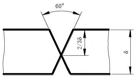
[0019] A CO for ultra-high-strength thick steel plates 2 Welding method of gas shielded welding. First process the groove on the ultra-high-strength thick steel plate to be welded after blanking, such as figure 1 As shown, the groove is an asymmetrical X shape, the angle of the groove is 60°, and the thickness of the upper groove is 2 / 3 of the thickness of the steel plate. CO 2 In the gas shielded welding method, the bottom layer welding and the filling layer welding are carried out in sequence, and then the nondestructive testing of the weld seam and the mechanical performance testing of the welded joint are carried out by ultrasonic waves. In this embodiment, no preheating is required before welding, interlayer temperature control is not required during welding, and slow cooling is not required after welding.

[0020] The bottom layer welding in this embodiment adopts 500MPa level welding wire ER50-6, the welding wire diameter is 1.2mm, and the bottom layer thickness is 5...

Embodiment 2

[0026] A CO for ultra-high-strength thick steel plates 2 Welding method of gas shielded welding. First process the groove on the ultra-high-strength thick steel plate to be welded after blanking, such as figure 1 As shown, the groove is an asymmetrical X shape, the angle of the groove is 60°, and the thickness of the upper groove is 2 / 3 of the thickness of the steel plate. CO 2 In the gas shielded welding method, the bottom layer welding and the filling layer welding are carried out in sequence, and then the nondestructive testing of the weld seam and the mechanical performance testing of the welded joint are carried out by ultrasonic waves. In this embodiment, no preheating is required before welding, interlayer temperature control is not required during welding, and slow cooling is not required after welding.

[0027] The primer welding in this embodiment uses 600MPa-grade welding wire ER60-6 with a diameter of 1.2mm and a thickness of 2-5mm for the primer; the filler lay...


PUM

PropertyMeasurementUnit
thicknessaaaaaaaaaa
strengthaaaaaaaaaa
thicknessaaaaaaaaaa

Abstract

The invention relates to a welding method for CO2 gas shielded welding for a super-strength thick steel plate. According to the technical scheme of the welding method, a groove is machined in the blanked to-be-welded super-strength thick steel plate and is in an asymmetric X shape; and bottoming layer welding and filling layer welding are sequentially conducted through a CO2 gas shielded welding method, nondestructive testing is conducted on a welding line through ultrasonic waves, and mechanical performance testing is conducted on a welding connector. According to bottoming layer welding, a welding stick of the 500-600 MPa level is used for performing welding, and the thickness of a bottoming layer ranges from 2 mm to 8 mm; and according to filling layer welding, a welding stick with the strength equal to the strength of base metal is adopted for welding. The strength of the to-be-welded super-strength thick steel plate is larger than or equal to 890 MPa, and the thickness of the to-be-welded super-strength thick steel plate ranges from 25 mm to 30 mm. The welding method has the beneficial effects of being simple in technology, low in manual strength, low in welding cost and high in welding efficiency. The welding connector formed through the welding method obtains the good comprehensive mechanical performance and is suitable for super-strength large thick plate structural steel with strength being larger than or equal to 890 MPa.

Description

technical field [0001] The invention belongs to CO 2 Gas shielded welding technology field. Specifically relates to a CO for ultra-high strength thick steel plate 2 Welding method of gas shielded welding. Background technique [0002] In recent years, structural steel has continuously developed towards the direction of ultra-high strength and large structures. Requirements for large components such as construction machinery. [0003] Such high-performance steel materials usually add higher alloy content, such as C, Mn, Cr, Mo and Ni, etc., to ensure the strength, toughness, fatigue and corrosion resistance, and the high alloy content also directly improves the carbon content of the material. The equivalent (Ceq) and cold crack sensitivity coefficient (Pcm) bring difficulties to the subsequent welding process. Therefore, when welding such ultra-high-strength thick plates, it is necessary to preheat before welding, control interlayer temperature and slow cooling after wel...

Claims


Application Information

Patent Timeline
Patent Type & Authority Applications(China)
IPC IPC(8): B23K9/16B23K101/18
CPCB23K9/16B23K2101/18
Inventor 王红鸿吴开明李军辉魏然黄刚
Owner WUHAN UNIV OF SCI & TECH
Why Eureka
Try Eureka