
Dual-station discharge mechanism

A dual-station, station technology, applied in the direction of conveyor objects, transportation and packaging, packaging, etc., can solve problems such as the impact of the production efficiency of the assembly line, the blockage of the machine tool discharge channel, and the large amount of product transfer. The effect of taking efficiency, improving processing efficiency and smooth discharging

Inactive Publication Date: 2016-06-08
SUZHOU BEITELUO INTELLIGENT TECH CO LTD
View PDF6 Cites 9 Cited by
  • Summary
  • Abstract
  • Description
  • Claims
  • Application Information

AI Technical Summary

Problems solved by technology

Existing machine tools or punching machines have high processing efficiency, which also leads to a large amount of product transfer. It is often difficult for a single-station unloading bin or corresponding unloading mechanism to meet the needs of unloading, and the full bin needs to be temporarily removed for unloading. position to clear the warehouse, at this time, the discharge port of the machine tool needs to be closed or do other processing, which will cause a short-term blockage of the discharge channel of the machine tool to a certain extent, and will also affect the production efficiency of the assembly line

Method used


Image

  • Dual-station discharge mechanism
  • Dual-station discharge mechanism

Examples


Embodiment

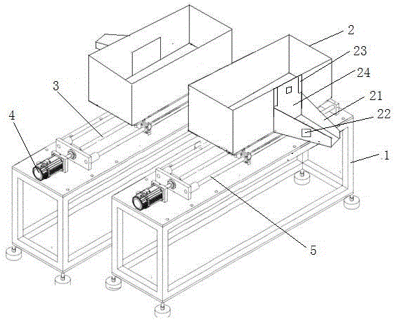
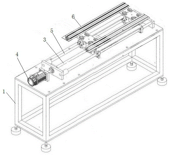
[0018] combine figure 1 with figure 2 In the illustrated embodiment, the moving track of the silo is two guide rails 5 parallel to the screw rod 3 and arranged on both sides of the screw rod, and the bin mounting frame 6 is slidably connected to the two guide rails 5 . The arrangement of double guide rails can make the movement of the material bin 2 more stable. The screw mandrel 3 is connected to the output shaft of the driving motor through a coupling, and the driving motor 4 can be selected from an existing stepping motor.

[0019] The silo 2 is provided with a discharge port, the discharge port is provided with a discharge baffle 24, the two sides of the discharge port are provided with a retaining bar 23, and the both sides of the discharge baffle 24 are snapped into the retaining bar 23 and the receiving bin 2. between the walls, and can move up and down to cover or keep away from the outlet.

[0020] When the discharge baffle 24 is opened, in order to make the mater...


PUM


Abstract

The invention discloses a dual-station discharge mechanism which comprises a support. The support is provided with a first station and a second station side by side. The first station and the second station each comprise a material collecting bin, a material bin installing frame, a material bin movement rail and a material bin drive unit. Each material collecting bin is installed on the corresponding material bin installing frame. The material bin movement rails of the first station and the second station are parallel to each other. Each material bin drive unit comprises a drive motor and a lead screw, wherein the lead screw is installed on the support in the mode that the lead screw is parallel to the corresponding material bin movement rail, one end of the lead screw is connected with an output shaft of the drive motor, the other end of the lead screw is connected with the corresponding material bin installing frame in a rotating mode and penetrates through the material bin installing frame, and the corresponding material bin installing frame can be driven by the rotating lead screw to move along the corresponding material bin movement rail. By means of the material collecting bins of the two stations, there is no need to wait until the material bins are emptied on a machining assembly line, discharge can be continuously conducted, the material collecting efficiency can be greatly improved, and the improvement of the product machining efficiency is facilitated.

Description

technical field [0001] The invention relates to machine tool blanking technology, in particular to a double-station blanking mechanism. Background technique [0002] As the automation level of industrial processing lines is getting higher and higher, the processing efficiency has also been improved accordingly. The semi-finished products or finished products processed by punching machines or machine tools need to be transferred from the production line to the middle of the next step of processing or finished product packaging. Corresponding position, in order to facilitate further operation. Existing machine tools or punching machines have high processing efficiency, which also leads to a large amount of product transfer. It is often difficult for a single-station unloading bin or corresponding unloading mechanism to meet the needs of unloading, and the full bin needs to be temporarily removed for unloading. position to clear the warehouse, at this time, the discharge port ...

Claims


Application Information

Patent Timeline
Patent Type & Authority Applications(China)
IPC IPC(8): B65G47/44
CPCB65G47/44B65G2207/30
Inventor 黄文卿
Owner SUZHOU BEITELUO INTELLIGENT TECH CO LTD
Learn More