Directional static blasting construction method for foundation pit stratum and combined guiding device for directional static blasting construction method

A static blasting and construction method technology, applied in blasting, infrastructure engineering, excavation, etc., can solve the problems of difficult to determine the effect of blasting, unclear surface conditions, complex device structure, etc., to improve blasting efficiency, structure and structure. Simple processing and convenient materials

Active Publication Date: 2016-06-08
湖南航天建筑工程有限公司
View PDF8 Cites 22 Cited by
  • Summary
  • Abstract
  • Description
  • Claims
  • Application Information

AI Technical Summary

Problems solved by technology

There are three deficiencies in this device and method: First, the device has a complex structure, and its designed outer diameter is consistent with the borehole diameter, which requires high aperture and verticality of the blasting hole, but the blasting drilling system is artificially assisted. Construction, deviations are easy to occur during the construction process, and it is difficult to install with slight deviations
Second, when the device is installed, the tip of the splitting angle of the steel formwork is required to be on the same straight line as the pre-split line; it is time-consuming to ensure that the tip of the splitting angle in all drilling holes is consistent with the pre-split line during actual operation
Third, the conditions of the air surface for blasting are not clear, and the effect of blasting is difficult to determine

Method used

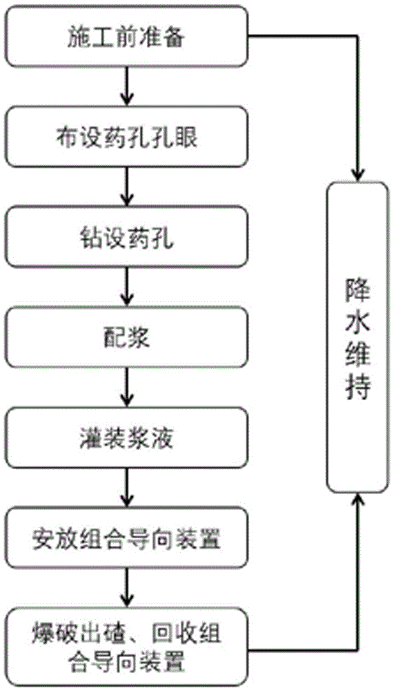
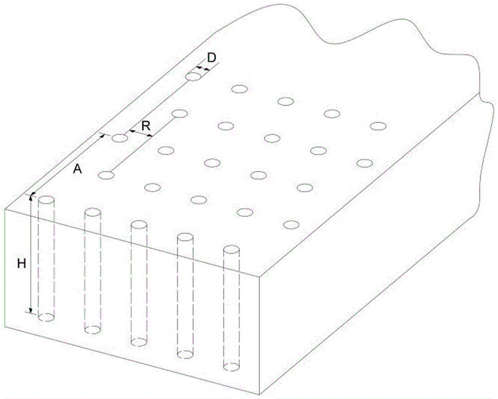

Image

  • Directional static blasting construction method for foundation pit stratum and combined guiding device for directional static blasting construction method
  • Directional static blasting construction method for foundation pit stratum and combined guiding device for directional static blasting construction method
  • Directional static blasting construction method for foundation pit stratum and combined guiding device for directional static blasting construction method

Examples


Embodiment Construction

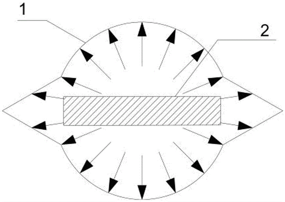
[0055] The present invention will be further described by taking the excavation construction of foundation pit rock layer in the space required for the installation of escalators in Aizhai Sightseeing Elevator Project as an example and in conjunction with the accompanying drawings.

[0056] refer to figure 1 , the technological principle on which the present invention is based is as follows:

[0057] (1) The main component of the silent crushing agent (HSCA) is CaO, which generates Ca(OH) after mixing with water 2 , in the free state, Ca(OH) 2 The volume expansion is about 3 times that of CaO, and the porosity also increases accordingly, no expansion pressure is generated, only the volume expands; but in the state where the expansion space is limited, Ca(OH) 2 When the volume increases, they squeeze each other, and the porosity becomes smaller, resulting in expansion pressure, and this solid expansion becomes the driving force for breaking rocks.

[0058] (2) In the drillin...


PUM


Abstract

The invention discloses a directional static blasting construction method for a foundation pit stratum and a combined guiding device for the directional static blasting construction method. The directional static blasting construction method for the foundation pit stratum comprises the first step of field testing, the second step of chemical hole opening arranging, the third step of chemical hole drilling, the fourth step of grout preparing, the fifth step of grout filling, the sixth step of combined guiding device arranging, the seventh step of blasting, slag discharging and combined guiding device recycling and the eighth step of dewatering maintaining. The combined guiding device for directional static blasting is formed by combining long-strip steel sheets and a metal square pipe with guiding square holes for the long-strip steel sheets to penetrate. The long-strip guiding steel sheets are placed in static blasting chemical holes, and consequently penetrating main cracks are generated by a rock mass in the width direction of the long-strip steel sheets. Meanwhile, compared with a conventional static blasting method, the distance of the chemical holes is increased by 1.3-1.5 times in the method, the effect of directional rock mass fracturing is achieved, and meanwhile the blasting efficiency is improved.

Description

technical field [0001] The invention belongs to the field of building construction, and in particular relates to a directional static blasting construction method for foundation pit rock formations and a combined guiding device thereof. Background technique [0002] At present, in engineering construction projects, traditional explosives are mostly used in the excavation of underground rock layers for blasting construction; explosives may cause potential safety hazards to the surrounding environment and personnel during the process of handling, storage and use. [0003] The static breaking agent has the characteristics of hydration reaction and volume expansion when it encounters water; the static breaking agent and water or the silent breaking agent and water are prepared in a certain proportion to form a uniform slurry, which is poured into the holes of the rock body to be broken. The hydration reaction proceeds; the silent breaking agent generates a large expansion pressu...

Claims


Application Information

Patent Timeline
Patent Type & Authority Applications(China)
IPC IPC(8): F42D3/04F42D1/00E02D17/02
CPCE02D17/02F42D1/00F42D3/04
Inventor 刘玉柱
Owner 湖南航天建筑工程有限公司
Why Eureka
Try Eureka