Wave aberration detection system and detection method using knife edge as detection mark

A detection mark and detection system technology, applied in the direction of geometric characteristics/aberration measurement, test optical performance, etc., can solve the problem of increasing the complexity of detection equipment and test time, the difficulty of accurately measuring the spatial distribution of detection marks, and the difficulty of accurately determining the position of detection marks, etc. question

Active Publication Date: 2018-04-17
SHANGHAI INST OF OPTICS & FINE MECHANICS CHINESE ACAD OF SCI
View PDF5 Cites 0 Cited by
  • Summary
  • Abstract
  • Description
  • Claims
  • Application Information

AI Technical Summary

Problems solved by technology

Although Ptychography technology can achieve high-precision measurement in the field of wave aberration detection, it has the following disadvantages: 1) The introduction of detection marks with complex patterns and the need for multiple scanning operations increase the complexity of the detection equipment and the system. 2) the spatial distribution of the detection mark is difficult to measure accurately, 3) the position of the detection mark under multiple scans relative to the illumination light wave is difficult to accurately determine

Method used


Image

  • Wave aberration detection system and detection method using knife edge as detection mark
  • Wave aberration detection system and detection method using knife edge as detection mark
  • Wave aberration detection system and detection method using knife edge as detection mark

Examples


Embodiment Construction

[0084] The present invention will be further described below in conjunction with the examples and drawings, but the examples should not limit the protection scope of the present invention.

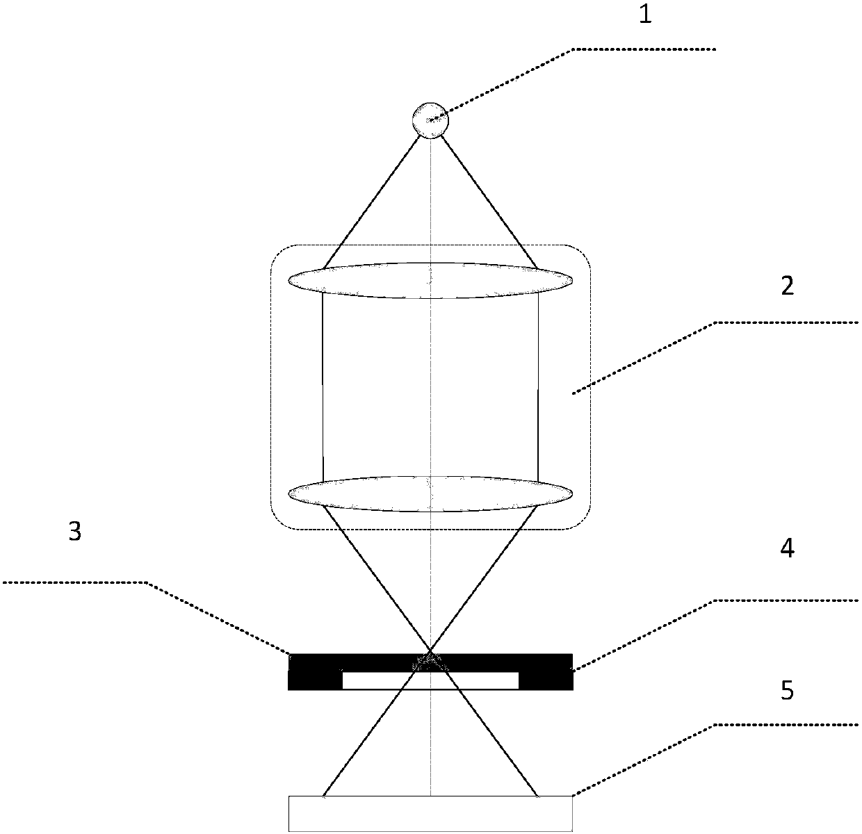
[0085] figure 1 It is the optical path diagram of the wave aberration detection system using the knife edge as the detection mark in the present invention, including a coherent point light source 1, and along the light beam propagation direction of the point light source 1 are the projection objective lens 2 to be tested, the knife edge pattern 3 as the detection mark, and the fixed knife edge pattern The detection mark adjusts the displacement stage 4 and the two-dimensional photoelectric sensor 5 . The coherent point light source 1 is located on the object surface of the projection objective lens 2 to be measured, the knife-edge pattern 3 is fixed on the detection mark adjustment displacement table 4, and the detection mark adjustment displacement table 4 is placed on the On the image p...


PUM


Abstract

The invention discloses a wave aberration detecting system with a knife edge as a detection marker and a wave aberration detecting method based on the knife-edge testing technology and the Ptychography technology. The wave aberration detecting system comprises a coherent point light source, a knife-edge graph serving as the detection marker, a detection-marker adjusting displacement platform for fixing the knife-edge graph and a two-dimensional photoelectric sensor. As the wave aberration of a to-be-detected projection lens is detected through the wave aberration detecting system, the system structure can be simplified, the collecting times of an observation surface pattern are decreased, and the detecting speed and the detecting accuracy of the system are increased.

Description

technical field [0001] The invention relates to a wave aberration detection system and a detection method, in particular to a wave aberration detection system using a knife edge as a detection mark and a wave aberration detection method based on a knife edge test technology and scanning coherent diffraction imaging (Ptychography) technology. Background technique [0002] Wave aberration detection technology can be roughly divided into two categories: one is wave aberration detection technology based on pupil plane measurement, including Shack-Hartmann sensor, point diffraction interferometer and shear interferometer, etc.; the other is based on space Wave aberration detection technology for image measurement. The two types of technical styles are very different but each has its own merits. From the perspective of technical means, the former extracts the wavefront information from the current detection results through some technical means (such as the Shack-Hartmann sensor e...

Claims


Application Information

Patent Timeline
Patent Type & Authority Patents(China)
IPC IPC(8): G01M11/02
CPCG01M11/0242
Inventor 方伟唐锋王向朝朱鹏辉李杰
Owner SHANGHAI INST OF OPTICS & FINE MECHANICS CHINESE ACAD OF SCI
Why Eureka
Try Eureka