
Differential signal amplitude detection circuit

A technology of amplitude detection and differential signal, which is applied in the field of differential signal amplitude detection circuit, can solve the problems of inability to perform differential small signal detection, single-ended output amplitude cannot follow differential input signal amplitude, and low conversion efficiency of differential signal amplitude detection circuit, etc.

Active Publication Date: 2016-06-08
FENGHUO COMM SCI & TECH CO LTD
View PDF10 Cites 4 Cited by
  • Summary
  • Abstract
  • Description
  • Claims
  • Application Information

AI Technical Summary

Problems solved by technology

[0006] The technical problem to be solved by the present invention is that the conversion efficiency of the existing differential signal amplitude detection circuit is low. problem with signal detection

Method used


Image

  • Differential signal amplitude detection circuit
  • Differential signal amplitude detection circuit
  • Differential signal amplitude detection circuit

Examples


Embodiment Construction

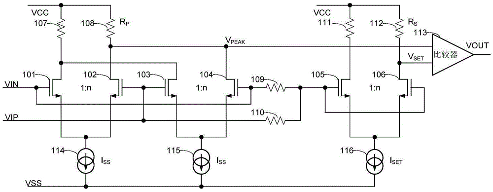
[0048] The invention converts the differential input signal into a single-ended non-polarity output signal by using two groups of asymmetric common-emitter or common-source circuits in parallel, and at the same time amplifies the signal so that the single-ended output amplitude can follow the differential input signal amplitude, and even higher, so normal amplitude detection is also possible in differential small signal mode. The present invention can be implemented on a CMOS (Complementary Metal Oxide Semiconductor, Complementary Metal Oxide Semiconductor) process or a BiCMOS (Bipolar CMOS, a technology in which CMOS and bipolar devices are simultaneously integrated on the same chip) process.

[0049] The present invention will be described in detail below in conjunction with the accompanying drawings and specific embodiments.

[0050] Such as figure 1 As shown, it is a differential signal amplitude detection circuit diagram provided by Embodiment 1 of the present invention,...


PUM


Abstract

The invention discloses a differential signal amplitude detection circuit. Grid electrodes of a first NMOS tube and a second NMOS tube are connected with a negative input end and a positive input end. Source electrodes of the first NMOS tube and the second NMOS tube are connected and are grounded through a first constant current source. Grid electrodes of a third NMOS tube and a fourth NMOS tube are connected with the positive input end and the negative input end. Source electrodes of the third NMOS tube and the fourth NMOS tube are connected and are grounded through a second constant current source. Drain electrodes of the first NMOS tube and the third NMOS tube are connected and are connected with a power supply through a first resistor. Drain electrodes of the second NMOS tube and the fourth NMOS tube are connected to form a first connection point and are connected with the power supply through a second resistor. A connection point between a third resistor and a fourth resistor is connected with grid electrodes of a fifth NMOS tube and a sixth NMOS tube. Source electrodes of the fifth NMOS tube and the sixth NMOS tube are connected and are grounded through a third constant current source. Drain electrodes of the fifth NMOS tube and the sixth NMOS tube are connected with the power supply through a fifth resistor and a sixth resistor. The connection point between the sixth NMOS tube and the sixth resistor is a second connection point. The first connection point and the second connection point are connected with two input ends of a comparator, and VOUT is output. The differential signal amplitude detection circuit has the advantages that the structure is simple, the power consumption is low, a small differential signal of a millivolt level can be effectively detected, and the application range is wide.

Description

technical field [0001] The invention relates to the technical field of analog signal processing and communication, in particular to a differential signal amplitude detection circuit. Background technique [0002] As a basic analog circuit, the differential signal amplitude detection circuit is widely used in data sampling. In communication systems, it is often necessary to judge whether the normal transmission signal has been interrupted as a system alarm condition, or to turn on the sleep mode to save power consumption. [0003] When a high-speed signal is transmitted, it is generally a differential signal with a low differential amplitude. At this time, it is necessary to detect a small differential amplitude, sometimes even only a few millivolts. For example, the limiting amplifier in the 10GSFP+ optical module, the laser driver and In the 10G multiplexing and demultiplexing chips, it is necessary to detect whether the input signal is lost, and the differential amplitude ...

Claims


Application Information

Patent Timeline
IPC IPC(8): G01R19/04
CPCG01R19/04
Inventor 许胜国程妮
Owner FENGHUO COMM SCI & TECH CO LTD
Learn More