A laser phase ranging module

A phase ranging and laser technology, which is applied in measuring devices, radio wave measuring systems, electromagnetic wave re-radiation, etc., can solve the problems of limited measuring distance, increased measuring distance echo, and difficulty in obtaining, etc., and achieves simple processing algorithms, The effect of simple processing circuit and simple algorithm

Active Publication Date: 2018-04-06
UNIV OF ELECTRONICS SCI & TECH OF CHINA
View PDF5 Cites 0 Cited by
  • Summary
  • Abstract
  • Description
  • Claims
  • Application Information

AI Technical Summary

Problems solved by technology

In order to increase the measurement range without increasing the complexity of the circuit as much as possible, the indirect measuring ruler method is generally used, that is, two or more short measuring rulers are used to equivalent long measuring rulers, so measuring a target point requires Perform frequency switching several times. During the switching process, it is necessary to wait for enough time to ensure the stability of the signal, so it is not good for fast measurement, especially for the situation where multiple simultaneous fast ranging is required.
In addition, the laser phase range finder uses semiconductor lasers as the emission light source. Semiconductor lasers that can achieve high-power and high-speed modulation are relatively expensive and difficult to obtain, while low-power semiconductor lasers cause the measurement distance to be limited. To increase the measurement distance, it is often necessary to equip prisms or reflectors to enhance the echo, so it needs to pay a higher cost to achieve the distance measurement of distant uncooperative targets

Method used


Image

  • A laser phase ranging module
  • A laser phase ranging module
  • A laser phase ranging module

Examples


Embodiment Construction

[0017] The present invention will be further described in detail below with reference to the drawings and embodiments.

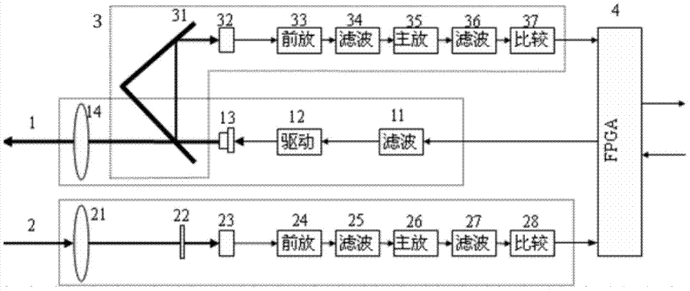
[0018] Such as figure 1 Shown is a schematic diagram of the principle of the laser phase ranging module of the present invention.

[0019] The active crystal oscillator provides a 100MHz clock input for the FPGA. Two clock frequencies are generated by phase-locking. One of them is 100MHz. The frequency is divided by 100MHz to generate a 1MHz square wave. After filtering, it becomes a 1MHz sine wave and drives the laser to emit. The range is 150m; To obtain a measurement accuracy of 1.5mm, N=1000 is required. If M=1, Δf is required to be 1kHz. It is very difficult to generate such a difference frequency by the phase-locked loop of the FPGA. Separately select the value of M; select a dual-phase-locked loop FPGA, and generate another clock of 100.043MHz through cascade mode as the square wave A and B data read clock. At this time, M=43, and N / M cannot be simplified....


PUM


Abstract

The invention relates to laser ranging technology, and provides a laser phase ranging module, including a laser emitting component, an echo receiving and preprocessing component, a local receiving and preprocessing component, and an FPGA processor; the FPGA processor uses a phase-locked loop to generate two Two clock frequencies f1 and f2 are divided by the clock frequency f1 to generate a square wave signal with a measuring ruler frequency fs and send it to the laser emitting component; the laser emitting component emits laser light to the target; the echo reflected by the target is received and preprocessed After processing, the component outputs a square wave A with a frequency of fs; the local receiving and preprocessing component imports the emitted laser part, and performs the same preprocessing on the imported laser as the echo receiving and preprocessing component to output square wave B; the FPGA processor uses a clock The frequency f2 reads the two square waves A and B synchronously, and calculates the target distance through data processing. The invention does not need frequency mixing processing, can realize long-distance precision distance measurement by using a measuring ruler, and is suitable for single-point distance measurement and multi-channel simultaneous distance measurement equipment.

Description

Technical field [0001] The present invention relates to laser ranging technology, mainly relates to laser ranging technology using phase detection, specifically a laser phase ranging module. Background technique [0002] The laser phase ranging technology measures the distance by detecting the phase delay caused by the target echo. Laser phase ranging often uses two optical paths, one is the target measurement optical path, and the other is the reference zero-calibration optical path in this machine. The phase difference produced by the two output waveforms corresponds to the distance value of the target. There are many phase ranging schemes, and the main difference lies in the way the photoelectric signal is processed. In the traditional laser phase ranging technology, a sine wave modulated laser is emitted, and the received echo is converted into an electrical signal through photoelectric conversion, and then mixed with a local signal using a mixer circuit to generate a low-fr...

Claims


Application Information

Patent Timeline
Patent Type & Authority Patents(China)
IPC IPC(8): G01S17/36G01S7/491
CPCG01S7/4911G01S7/4915G01S17/36
Inventor 彭仁军段逢源王凯
Owner UNIV OF ELECTRONICS SCI & TECH OF CHINA
Why Eureka
Try Eureka