
Vascular occlusion forceps easy to detach and clean and capable of being freely bent

A vascular blocking and easy-to-remove technology, applied in medical science, surgery, wound clips, etc., can solve the problems of affecting the use efficiency of the device, being difficult to use, and difficult to achieve a buffer effect, so as to improve the use efficiency and versatility, reduce The difficulty of operation and the effect of reducing the difficulty of handling

Active Publication Date: 2016-06-15
北京瑞克斡医疗科技有限公司
View PDF8 Cites 1 Cited by
  • Summary
  • Abstract
  • Description
  • Claims
  • Application Information

AI Technical Summary

Problems solved by technology

[0003] However, most of the current blocking forceps have specific structural shapes according to different operating environments, including arterial, venous, thoracic and pulmonary blocking forceps, and the shapes of each blocking forceps are different, making it difficult to use universally ; This makes the number of surgical instruments not only large and the types of instruments are also very complex, each operation must be rationally configured according to the surgical requirements, which not only increases the difficulty of the operation, but also is not conducive to reducing medical costs
[0004] The current blocking forceps not only have the above-mentioned shortcomings that are difficult to use universally, but also have a series of defects caused by the rigid connection of the structure and the rigid transmission of the control moment; for example, a minimally invasive ascending aortic blocking forceps disclosed in Chinese patent ZL201320684993. And the similar ZL200920218143.4 discloses a kind of thoracoscopic side angle vascular blocking forceps, they all adopt the integrated hinged structure of the handle and the jaw, and then design the handle or the jaw into a specific shape according to the actual needs. The torque from the handle directly acts on the state control of the jaws. Not only can it not buffer the control torque, but it is also difficult to actively change the shape of the blocking forceps to meet the special needs of the operation. have high operating requirements
[0005] In order to improve the operating efficiency of the blocking forceps, some blocking forceps with more advanced structures have also been designed, such as a detachable temporary blocking forceps for minimally invasive surgery disclosed in Chinese patent ZL201320684993. transfer, to control the design idea of ​​opening and closing the jaws, but this technical solution is not a blocking forceps directly used in medical operations, it needs to cooperate with an additionally designed "two-piece clamping clamp 21", and due to the use of rigid It is difficult to achieve the requirements of linear and smooth clamping of the jaws, and it is also difficult to reduce the operation of the blocking pliers. actual difficulty
[0006] The traditional blocking pliers are connected by an X-shaped cross shaft that is difficult to deform. This structure is generally short in length and the operating environment is limited, but the structure is simple and easy to clean; while the more advanced structural design that uses rods for torque transmission, although the degree of movement The above-mentioned defects are overcome, but the structure is complicated, and parts that are easy to accumulate dirt such as sleeves are used. It is very difficult to disassemble and clean the instruments after surgery, which affects the actual use efficiency of the instruments. Incomplete cleaning will not be conducive to the safety of surgical instruments. safe to use

Method used


Image

  • Vascular occlusion forceps easy to detach and clean and capable of being freely bent
  • Vascular occlusion forceps easy to detach and clean and capable of being freely bent
  • Vascular occlusion forceps easy to detach and clean and capable of being freely bent

Examples


Embodiment Construction

[0034] The specific embodiments of the present invention will be further described below in conjunction with the accompanying drawings.

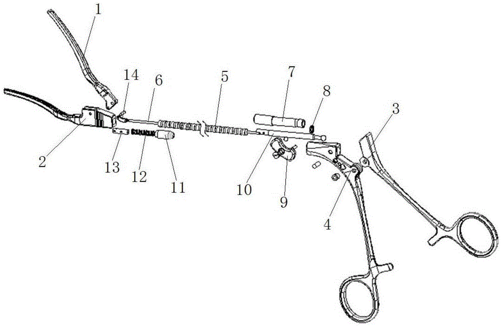
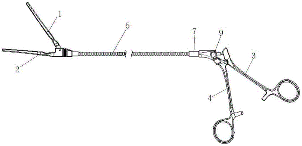
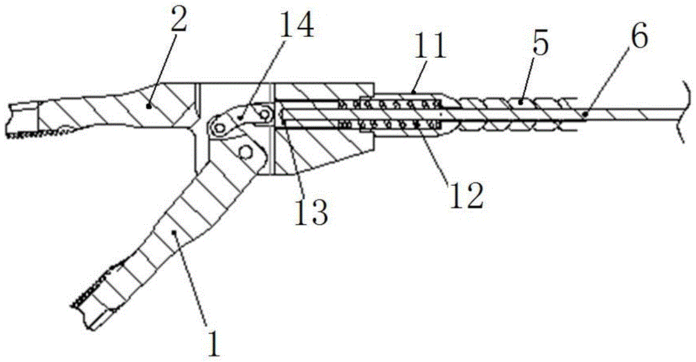
[0035] Such as Figure 1-Figure 7 As shown, the present invention is realized in such a way that the free-bending blood vessel blocking forceps that are easy to disassemble and clean include a handle and jaws that move under the control of the handle. The handle 4 and the moving handle 3, the jaws include the moving tongs 1 and the fixed tongs 2 which are connected together by shafts, a bendable metal tube 5 is connected between the fixed handle 4 and the fixed tongs 2, the moving handle 3 and the moving tongs 1 is connected with a flexible transmission part 6; in this way, the relative position of the handle and the jaw can be adjusted arbitrarily through the support of the metal tube 5, and the flexible transmission part 6 is responsible for transmitting the control torque of the handle to the jaw, and the flexible transmission part 6 can ...


PUM


Abstract

A pair of vascular occlusion forceps easy to detach and clean and capable of being freely bent comprises handles and a jaw moving under control of the handles. The handles comprise the fixed handle and the movable handle which are connected through a shaft. The jaw comprises a movable forceps body and a fixed forceps body which are connected through a shaft. A bendable metal pipe is connected between the fixed handle and the fixed forceps body. A flexible transmission element is connected between the movable handle and the movable forceps body. The fixed handle is connected with a guide sleeve through a steel ball clamping connection assembly easy to detach. One end of the flexible transmission element extends into the guide sleeve and is connected with a ball connection piece located in the guide sleeve, and the ball connection piece is connected to the movable handle in a clamped mode through a ball structure. The forceps can change into various shapes corresponding to an operation environment according to actual requirements, can achieve smoothness of control torque transmission and has a good buffering function on control torque between the handles and the jaw, parts where dirt is likely to accumulate can be conveniently detached and cleaned, and use efficiency of instruments can be effectively improved.

Description

technical field [0001] The invention relates to a blocking forceps, in particular to a freely bendable blood vessel blocking forceps which are easy to disassemble and clean. Background technique [0002] Blocking clamp is a commonly used medical device in surgery. It can block the blood flow path in blood vessels during surgery to avoid excessive blood loss in patients. It not only improves the blood circulation of patients during surgery, but also improves the success rate of surgery. . [0003] However, most of the current blocking forceps have specific structural shapes according to different operating environments, including arterial, venous, thoracic and pulmonary blocking forceps, and the shapes of each blocking forceps are different, making it difficult to use universally ; This makes the number of surgical instruments not only large and the types of instruments are also very complex, each operation will be rationally configured according to the operation of surgical...

Claims


Application Information

Patent Timeline
Patent Type & Authority Applications(China)
IPC IPC(8): A61B17/12
CPCA61B17/122A61B2017/12004
Inventor 刘鸿箫谢斌朱俊明顾承雄凌云鹏
Owner 北京瑞克斡医疗科技有限公司
Learn More