Desulphurization, denitration and dust removal integrated treatment process of exhaust gas

A technology for treating process and exhaust gas, which is applied in new processes and devices for integrated desulfurization treatment, glass and cement exhaust gas dedusting, and denitrification. Large and other problems, to achieve the effect of saving manpower maintenance and operating costs, operating cost savings, and low device operating costs

Inactive Publication Date: 2016-06-15
NANJING CEEP TECH
View PDF0 Cites 14 Cited by
  • Summary
  • Abstract
  • Description
  • Claims
  • Application Information

AI Technical Summary

Problems solved by technology

However, due to the particularity of the glass industry, that is, the dust particles are extremely small and have strong viscosity, there are some common problems in this process at present: 1) The efficiency of high-temperature electrostatic precipitator is difficult to reach the design efficiency; 2) The booster of the pole tube often fails , the system operation is unstable; 3) Due to the problem of high temperature electrostatic precipitator, the denitrification catalyst is quickly deactivated, so that the denitrification operation cannot reach the design efficiency for several months; 4) There are two dust removal processes in this process, the electrostatic precipitator process and the dry process The bag dust removal system necessary for desulfurization makes the system redundant, resulting in excessive investment and operating costs
The current research focus is on low-temperature denitrification, but there has been no success so far. It is imminent to develop a flue gas denitrification technology suitable for the cement industry; 3) Since the desulfurization of the cement industry is not currently the focus of national attention, the cement industry is basically not equipped with desulfurization devices

Method used


Image

  • Desulphurization, denitration and dust removal integrated treatment process of exhaust gas

Examples


Embodiment Construction

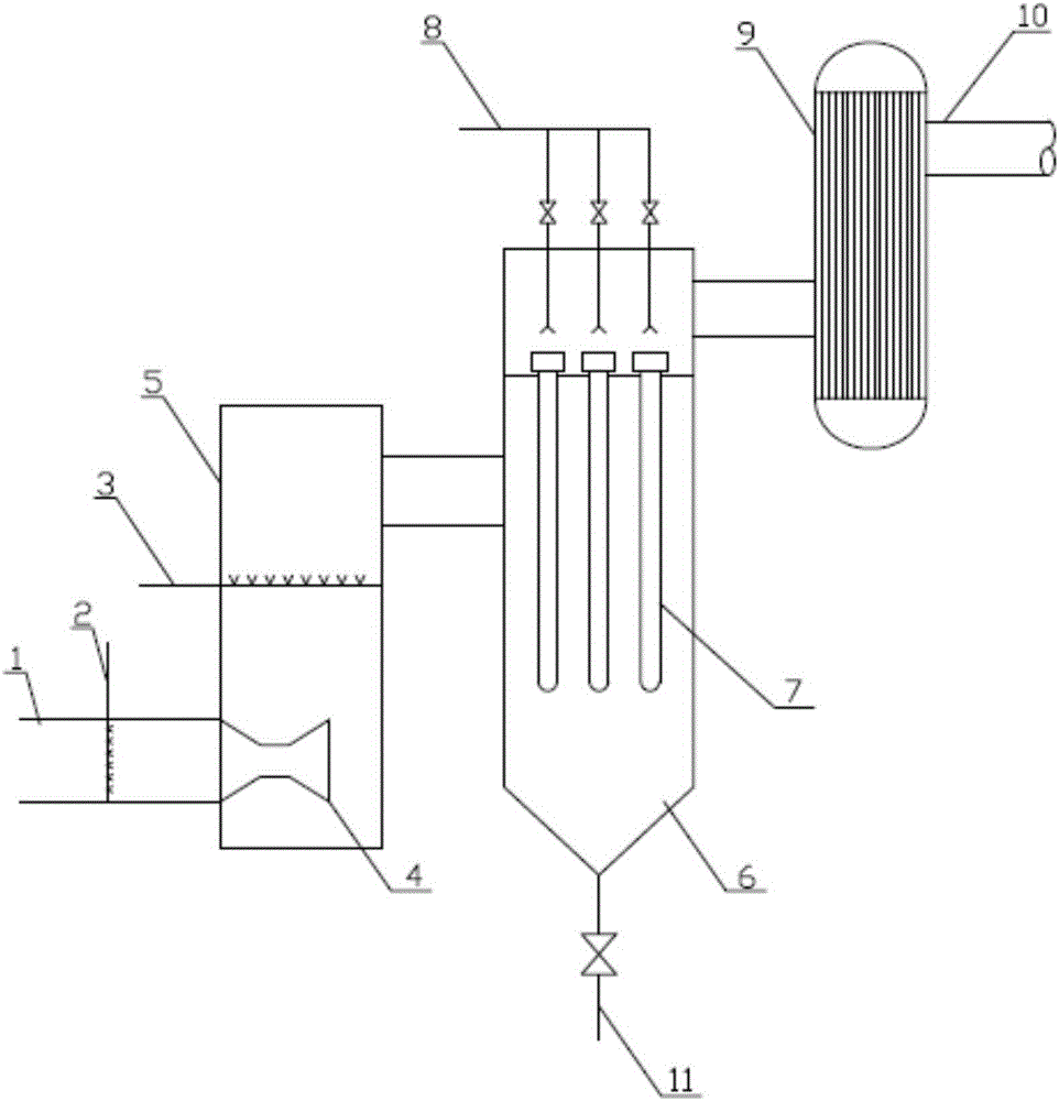
[0026] Taking flue gas denitrification in the cement industry as an example, figure 1 It is a schematic structural diagram of the new process device. As shown in the figure, the system mainly includes a desulfurizing agent injection device 2, a denitrification agent injection device 3, a flue gas mixing device 5, an integrated catalyst ceramic filter cartridge device 7, and an energy recovery device 9. The desulfurization agent injection device 2 is arranged on the inlet flue 1 of the device, and is injected into the flue gas mixing device 5 through the Venturi structure 4 for mixing and preliminary desulfurization reaction. In order to achieve higher desulfurization efficiency and reduce the consumption of desulfurization agent The flue gas mixing device 5 can be set as a circulating fluidized bed reaction tower, that is, part of the circulating ash is drawn from the dust collecting device 6 to the flue gas mixing device 5 to realize the recycling of incomplete reaction desulf...


PUM


Abstract

The invention relates to a desulphurization, denitration and dust removal integrated treatment process of exhaust gas. The treatment process comprises the following steps: introducing the flue gas into an integrated catalytic agent ceramic filter drum device at an appropriate temperature section, wherein the integrated catalytic agent ceramic filter drum device is provided with a back flushing ash removal device; injecting a desulphurization agent and a denitration agent before the exhaust gas enters the integrated catalytic agent ceramic filter drum device; arranging a flue gas mixing device in front of the integrated catalytic agent ceramic filter drum device; and introducing the treated flue gas reaching the standard into an energy recycling system to recycle the heat by virtue of a pressurizing fan, and finally discharging the flue gas into a chimney, wherein the appropriate temperature section is 280 to 420 DEG C. The process has the advantages of stable and reliable system, small maintenance workload, long product service life, low device operation cost and small device occupation area; and the flue gas flowing into a waste heat boiler is clean gas, so that the heat exchanging efficiency of the energy recycling device is greatly improved, the service life of the energy recycling device is greatly prolonged, and the economic benefit is vast.

Description

technical field [0001] The invention relates to the field of flue gas treatment, specifically an integrated process of desulfurization, denitrification and dust removal, especially a new process and device for integrated treatment of dust removal, denitrification and desulfurization of glass and cement tail gas. Background technique [0002] With the improvement of our country's economy and living standards, more and more attention will be paid to the environment. At present, environmental problems are deteriorating day by day. In the past two years, smog has shrouded six provinces and one city in East China, and it has a tendency to spread. PM2.5 monitoring systems in various places have also exploded one after another. At present, it has attracted widespread attention from the society. , Challenging the sensitive nerves of Chinese people. The country has also issued a series of policies in succession. The Ministry of Environmental Protection of the People's Republic of Ch...

Claims


Application Information

Patent Timeline
Patent Type & Authority Applications(China)
IPC IPC(8): B01D53/88B01D53/60B01D46/24B01D46/42F27D17/00
CPCB01D46/2411B01D53/8637B01D53/88F27D17/004B01D2259/124B01D2258/0283B01D2267/30F27D2017/006B01D46/72
Inventor 刘训稳韩冰陈勇邬世瑞
Owner NANJING CEEP TECH
Why Eureka
Try Eureka