Stepless speed change type vertical driller

A vertical drilling machine, stepless speed change technology, applied in the direction of boring machine/drilling machine parts, boring/drilling, drilling/drilling equipment, etc., can solve the problem of large size of vertical drilling machine, interrupted drill bit, inconvenient placement and other problems, to achieve the effect of stepless speed regulation, reduce the meshing coefficient, and facilitate the disassembly and assembly.

Inactive Publication Date: 2016-06-15
ZHEJIANG XILING
View PDF8 Cites 3 Cited by
  • Summary
  • Abstract
  • Description
  • Claims
  • Application Information

AI Technical Summary

Problems solved by technology

This directly increases the occupied area and volume of the vertical drilling machine, and due to the large size of the vertical drilling machine, it is inconvenient to place. At the same time, the meshing between the gears must be carefully checked during the installation of the partial cover. After running for a period of time, with the vibration of the vertical drilling machine, there will be deviations between the gears in the partial cover and the gears in the upper box, resulting in equipment failure, damage to parts, and failure to work normally
In addition, the structure adopted in the overload protection mechanism on the lower side of the lower countershaft is a single friction plate clutch structure. Such a structure will cause the torque carried by the overload protection mechanism to be too large under normal use. The drill bit and other shafts such as the sleeve cause strong torque, and even some faults such as twisting the shaft or breaking the drill bit may occur, which brings hidden dangers to safety in a high-speed operating environment

Method used


Image

  • Stepless speed change type vertical driller
  • Stepless speed change type vertical driller
  • Stepless speed change type vertical driller

Examples


Embodiment Construction

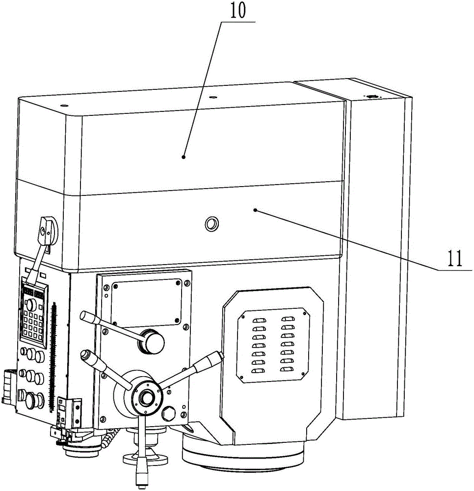
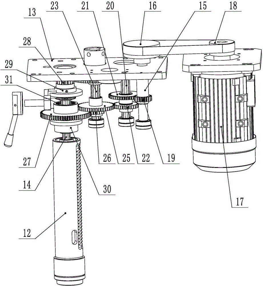
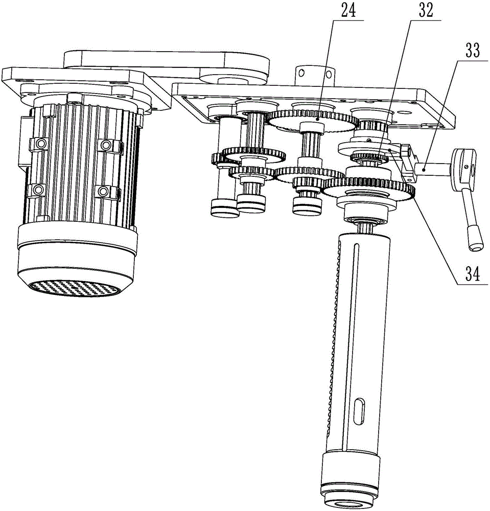
[0025] Reference Figure 1~3 , Is a continuously variable vertical drilling machine disclosed in the present invention. The casing is divided into upper and lower casings 10 and 11 by partitions. The lower casing 11 is provided with a sleeve 12 extending out of the lower casing 11 , The secondary shaft 14 is installed on the partition 13 in the lower box 11, the sleeve 12 is sleeved on the secondary shaft 14 and can slide axially along the secondary shaft 14, the partition on the side of the secondary shaft 14 in the lower box 11 13 is provided with a main shaft 15 penetrating through the partition 13 and the main shaft 15 penetrates the partition 13 and extends into the upper box body 10. The main shaft 15 in the upper box body 10 is equipped with a secondary transmission wheel 16, and the upper box body 10 or / and the lower box A permanent magnet motor 17 is installed on one side of the body 11, and a main transmission wheel 18 that drives the auxiliary transmission wheel 16 i...


PUM


Abstract

The present invention relates to the technical field of vertical drilling machine equipment, in particular to a continuously variable speed vertical drilling machine. The cabinet body is divided into upper and lower cabinets by partitions, and the lower cabinet is provided with a Sleeve, the auxiliary shaft is installed on the partition in the lower box, the sleeve is sleeved on the auxiliary shaft and can slide axially along the auxiliary shaft, and the main shaft passing through the partition is arranged on the partition on the side of the auxiliary shaft in the lower box , the main shaft extends through the partition to the upper box, and the auxiliary transmission wheel is installed on the main shaft in the upper box, and a permanent magnet motor is installed on one side of the upper box or/and the lower box, and a drive is installed on the motor shaft of the permanent magnet motor. The main transmission wheel that the secondary transmission wheel rotates, the main shaft in the lower casing is provided with the main gear that drives the secondary shaft to rotate, and the speed of the permanent magnet motor is controlled by the controller or by remote control. The advantages are: easy installation, reduced equipment volume and manufacturing costs, and at the same time can reduce the occurrence of failures, increase service life, improve work efficiency, and make products more intelligent.

Description

Technical field [0001] The invention relates to the technical field of vertical drilling machine equipment, in particular to a continuously variable speed vertical drilling machine. Background technique [0002] Vertical drilling machines are widely used in machinery manufacturing and processing industries such as drilling and tapping. At present, the traditional vertical drilling machine includes upper and lower boxes separated by partitions. The lower box is provided with a sleeve extending from the lower box, and the upper box is provided with the lower box. The upper counter shaft in the lower box is sleeved with a sleeve that can slide axially along the upper counter shaft. The partition on one side of the upper counter shaft is provided with a lower main shaft penetrating through the partition. One side of the lower main shaft is provided with a lower middle shaft, and one side of the lower middle shaft is provided with a lower counter shaft. Power is transmitted between t...

Claims


Application Information

Patent Timeline
Patent Type & Authority Applications(China)
IPC IPC(8): B23B39/10B23B47/06B23Q5/16B23B39/08
CPCB23B39/10B23B39/08B23Q5/16
Inventor 杨学良
Owner ZHEJIANG XILING
Why Eureka
Try Eureka