
Printing method of 3D printer with three-dimensional graphic feedback system

A 3D printer and feedback system technology, applied in the field of 3D printing, can solve the problems of inability to feedback and control the printing effect, waste of debugging man-hours and materials, and semi-finished products that cannot be reused, so as to improve printing efficiency, improve efficiency, and ensure stability. Effect

Inactive Publication Date: 2017-09-08
MATERIAL INST OF CHINA ACADEMY OF ENG PHYSICS
View PDF5 Cites 8 Cited by
  • Summary
  • Abstract
  • Description
  • Claims
  • Application Information

AI Technical Summary

Problems solved by technology

[0004] (1) Poor forming accuracy: In the prior art, the two processes of model slicing and printing are in an open-loop series relationship, the printing process cannot provide feedback and control on the printing effect, and unqualified products are blindly printed;
[0005] (2) Low printing efficiency: On the one hand, each workpiece needs to be printed from scratch, which greatly increases the printing time; on the other hand, semi-finished products produced by system failures or printing failures cannot be reused, and engineers can only adjust the model and parameters. Printing, consuming debugging man-hours and materials

Method used


Image

  • Printing method of 3D printer with three-dimensional graphic feedback system
  • Printing method of 3D printer with three-dimensional graphic feedback system
  • Printing method of 3D printer with three-dimensional graphic feedback system

Examples


Embodiment 1

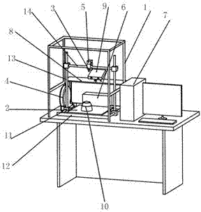
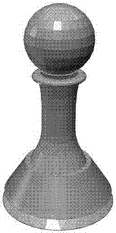
[0065] image 3 For the three-dimensional model A of the target product in Example 1, calculate and slice the three-dimensional model A, set the printing progress corresponding to 3D scanning in the generated slice file to 70%, then the control system reads the slice file, and starts from the first layer Layer-by-layer printing starts. When the printing progress reaches 70%, Figure 4 In order to control the system 6 to read the printed physical map when the scanning command is read, the control drive device remains in place, the temperature of the printing nozzle 3 is lowered, and the printing is suspended; at the same time, the 3D scanner is called to perform 3D scanning of the printed part 10, and the scanned data Synchronously sent to the computer 7, the computer establishes the three-dimensional model B of the printed part through image processing, such as Figure 5 shown.

[0066] The computer compares the 3D model B of the printed part with the 3D model A of the targ...

Embodiment 2

[0068] Figure 7 It is the three-dimensional model A of the target product in Embodiment 2. The difference between Embodiment 2 and Embodiment 1 is that the printing progress corresponding to the 3D scanning is set to 100%, and the 3D scanner is called to Figure 8 The printed object is scanned and created Figure 9 The 3D model B of the computer comparison data is: E1%, indicating that the deviation between the printed product and the target product has exceeded the set value, and the system determines that the product needs to be processed manually. Figure 9 The printed physical 3D model and Figure 7 It can be seen from the 3D model A of the target product that the multi-printed part D mainly comes from the top of the model, and then the top is manually processed to obtain Figure 10 real thing, yes Figure 10 The real object is 3D scanned again to get Figure 11 In the 3D model B’, the computer continues to Figure 11 The 3D model B' of Figure 7 Compared with the 3...


PUM


Abstract

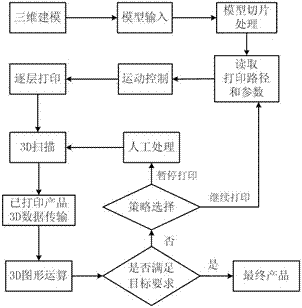
The invention discloses a 3D printing machine with a three-dimensional figure feedback system and a printing method of the 3D printing machine. The 3D printing machine comprises a rack, a printing platform, a printing spray head, a material box, a feeding device, a drive device, a control system, a computer, a support mounted on the outer side of the drive device and a 3D scanner which is arranged on the support and used for scanning a printed article. In the product forming process, the 3D scanner is used for scanning a semi-finished workpiece or a blank, the three-dimensional profile of the workpiece is obtained and compared with a three-dimensional model of a target product through graphics operation, the motion path and printing parameters of the printing machine are adjusted according to a result, and therefore feedback control of the printing process is achieved, and the 3D printing forming precision and the printing efficiency are improved.

Description

technical field [0001] The invention relates to the technical field of 3D printing, in particular to a printing method of a 3D printer with a three-dimensional graphics feedback system. Background technique [0002] 3D printing is a rapid prototyping technology, also called additive manufacturing technology. Compared with traditional manufacturing technology, its advantage is that it can realize the integration of design and manufacturing, reduce manufacturing costs and shorten the processing cycle, etc., and it has gradually been applied in the fields of biomedicine, industrial design, aerospace and cultural creativity. So far, a variety of rapid prototyping methods such as fused deposition (FDM), laser sintering (SLS), laser curing (SLA), three-dimensional printing (DLP) and three-dimensional laser engraving have been successfully developed at home and abroad, among which FDM is the most widely used. One of the broadest technologies. [0003] The basic principle of fused...

Claims


Application Information

Patent Timeline
Patent Type & Authority Patents(China)
IPC IPC(8): B29C64/118B33Y50/02
CPCB33Y50/02
Inventor 陈华明邓良才黄国强胡俊殷雪峰宋江锋
Owner MATERIAL INST OF CHINA ACADEMY OF ENG PHYSICS
Learn More