Full-automatic intelligent hydraulic workover rig

A fully automatic, workover rig technology, applied in drilling equipment, drilling equipment and methods, and earthwork drilling, etc., can solve the problems of harsh working environment, high risk factor, waste of electric energy, etc., and achieve the effect of reasonable distribution

Active Publication Date: 2016-06-15
SHANDONG SHENGLI PETROLEUM EQUIP IND TECH RES INST
View PDF7 Cites 19 Cited by
  • Summary
  • Abstract
  • Description
  • Claims
  • Application Information

AI Technical Summary

Problems solved by technology

[0002] In traditional oil field workover operations, the hydraulic energy storage workover rig used, especially when lifting the tubing string, the two motors are always in the full displacement working state, resulting in a great waste of electric energy, and An important issue is that on-site workover operations in the oil field require several workers to perform pipe arrangement, pipe transfer and wellhead operations. The work of pipe arrangement, pipe transfer and wellhead operations is not only a harsh working environment, but also has a high risk factor. In response to the national "China To meet the requirements of "manufacturing 2025" and modern oilfield operations, a fully automatic intelligent hydraulic workover rig has been developed, which uses dynamic load following control technology to realize intelligent matching of energy and full automatic control of workover operations

Method used


Image

  • Full-automatic intelligent hydraulic workover rig
  • Full-automatic intelligent hydraulic workover rig
  • Full-automatic intelligent hydraulic workover rig

Examples


Embodiment Construction

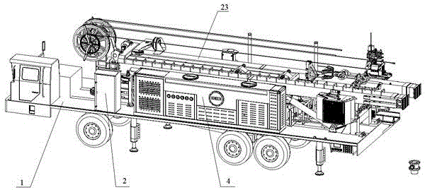
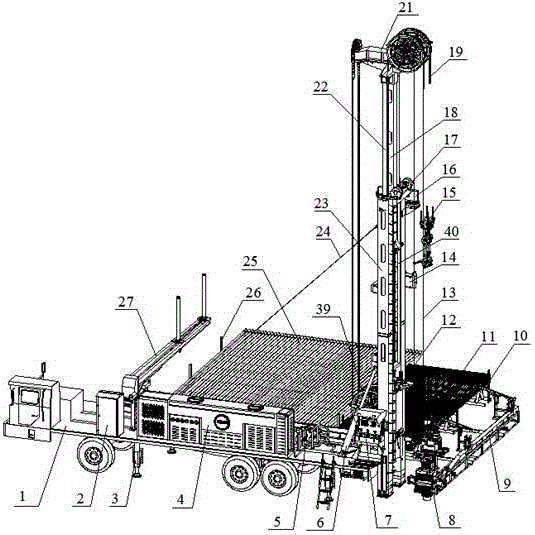
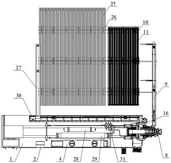
[0043] Such as Figure 1-20 As shown, a fully automatic intelligent hydraulic workover rig includes vehicle-mounted chassis 1, electric control cabinet 2, chassis outrigger 3, hydraulic station 4, energy storage compensation device 5, luffing cylinder 6, console 7, and automatic wellhead device 8. Automatic pipe arrangement mechanism 9, sucker rod pipe arrangement assembly 10, sucker rod 11, righting manipulator 12, flexible guide rail wire rope 13, small crane winch 14, hydraulic elevator 15, small crane 16, flexible guide rail winch 17 , master cylinder slide guide block 18, main wire rope 19, main wire rope fixed end 20, top driving device 21, main hydraulic cylinder 22, derrick 23, cable-stayed wire rope 24, oil pipe 25, oil pipe arrangement assembly 26, transfer pipe Mechanism assembly 27, accumulator 28, nitrogen bag 29, pipette guide rail 30, main valve block 31, pipette rack 32, pipette roller 33, pipette trolley 34, rotating mechanism assembly 35, pipette cantilever a...


PUM


Abstract

The invention relates to a full-automatic intelligent hydraulic workover rig. The full-automatic intelligent hydraulic workover rig comprises a vehicle-mounted chassis, an electric control cabinet, chassis support legs, a hydraulic station, an energy-accumulation compensating device, a derricking cylinder, an operation console, an oil sucker rod, an uplifting manipulator, a flexible guide rail steel wire rope, a small crane winch, a hydraulic elevator, a small crane, a flexible guide rail winch, a main cylinder guide rail, a main steel wire rope, a fixing end of the main steel wire rope, a top driving device, a main hydraulic cylinder, a derrick, an oblique steel wire rope, an oil pipe, an energy accumulator, a nitrogen bag, pipe moving guide rails, a main valve block, a pipe moving gear rack, pipe moving rollers, a pipe moving trolley, a rotary mechanism assembly, a pipe moving cantilever assembly, a pipe moving motor protecting cover, a pipe moving motor assembly and a main fixed pulley block, wherein an automatic pipe moving and arrangement system is arranged on the vehicle-mounted chassis, and comprises an automatic pipe arrangement mechanism, an oil sucker rod pipe arrangement device assembly, an oil pipe arrangement device assembly and a pipe moving mechanism assembly. The full-automatic intelligent hydraulic workover rig is suitable for the development requirements of intelligence of workover operation of an oilfield and automation of whole-process operation.

Description

technical field [0001] The invention relates to a fully automatic intelligent hydraulic workover rig, specifically a kind of equipment that intelligently adjusts the automatic speed of workover operations according to the weight of the hoisting tubing string, and can realize automatic pipe transfer and arrangement at the same time, belonging to the technical field of petroleum equipment . Background technique [0002] In traditional oil field workover operations, the hydraulic energy storage workover rig used, especially when lifting the tubing string, the two motors are always in the full displacement working state, resulting in a great waste of electric energy, and An important issue is that on-site workover operations in the oil field require several workers to perform pipe arrangement, pipe transfer and wellhead operations. The work of pipe arrangement, pipe transfer and wellhead operations is not only a harsh working environment, but also has a high risk factor. In resp...

Claims


Application Information

Patent Timeline
Patent Type & Authority Applications(China)
IPC IPC(8): E21B19/00E21B19/14E21B19/15E21B7/02
CPCE21B7/024E21B19/00E21B19/14E21B19/155
Inventor 刘化国古仁龙刘睿刘东李涛张金鹏刘凯泉白永涛
Owner SHANDONG SHENGLI PETROLEUM EQUIP IND TECH RES INST
Why Eureka
Try Eureka