Multi-channel jet flow vacuum pump

A jet vacuum pump and multi-channel technology, applied in the field of negative pressure suction equipment, can solve the problems of low nozzle bearing pressure, non-adjustable nozzle, twisted orifice, etc., achieve good cleaning performance, simplify structure, and increase bearing pressure.

Inactive Publication Date: 2016-06-15
蒋盘君
View PDF6 Cites 0 Cited by
  • Summary
  • Abstract
  • Description
  • Claims
  • Application Information

AI Technical Summary

Problems solved by technology

[0003] For the nozzles in the existing ejector, if the nozzles are clogged, use a soft brush or toothpick to clean it and be very careful during the cleaning process, which may distort the orifice. In addition, the existing nozzles have low bearing pressure and low efficiency. At the same time, The spout is not adjustable

Method used


Image

  • Multi-channel jet flow vacuum pump
  • Multi-channel jet flow vacuum pump

Examples


Embodiment

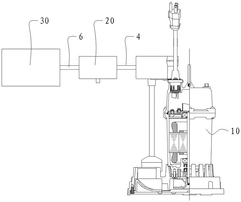
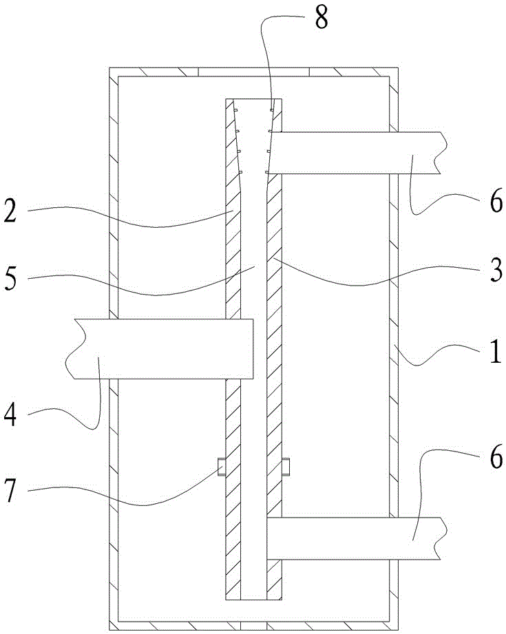
[0018] The multi-channel jet vacuum pump of the present embodiment, as figure 1 and figure 2 As shown, a submersible pump 10 , an ejector 20 and a vacuum tank 30 are included. The jet device 20 includes a jet box 1 with an outlet. The jet box 1 is provided with a left splint 2 and a right splint 3 that fit together. The center of the left splint 2 is provided with a jet liquid inlet that passes through the left splint 2 and is perpendicular to the left splint. Pipe 4, the inlet end of the jet liquid inlet pipe 4 is connected to the outlet of the submersible pump 10 .

[0019] Between the left splint 2 and the right splint 3, a plurality of jet nozzles 5 communicated with the jet liquid inlet pipe 4 are formed, and the plurality of jet nozzles 5 are evenly distributed along the center circumference of the jet liquid inlet pipe 4, and the aperture of each jet nozzle 5 is 8-20mm, the outlet end of each jet nozzle 5 is set opposite to the outlet of the jet box 1, and the edge o...


PUM


Abstract

The invention relates to a multi-channel jet flow vacuum pump, and belongs to the technical field of jet pumps for pumping liquid by utilizing inertia of pumped liquid. The multi-channel jet flow vacuum pump comprises a sinking pump, a jet flow device and a vacuum tank; the jet flow device comprises a jet flow box with an outlet, and a left clamping plate and a right clamping plate which are attached are arranged in the jet flow box; a jet flow liquid inlet pipe which penetrates the left clamping plate and is perpendicular to the left clamping plate is arranged on the center of the left clamping plate, and the inlet end of the jet flow liquid inlet pipe is communicated with an outlet of the sinking pump; a plurality of jet flow nozzles communicated with the jet flow liquid inlet pipe are formed between the left clamping plate and the right clamping plate and are circumferentially and evenly distributed along the center of the jet flow liquid inlet pipe; the hole diameter of each jet flow nozzle ranges from 8 mm to 20 mm, and the outlet end of each jet flow nozzle is arranged in a manner of being opposite to the jet flow box outlet; and an air inlet pipe communicated with each jet flow nozzle is arranged on the edge of the right clamping plate, and is communicated with a vacuum tank outlet. The multi-channel jet flow vacuum pump has the beneficial effects of being high in bearing pressure and good in cleaning performance.

Description

technical field [0001] The invention relates to a negative pressure suction device, which belongs to the technical field of jet pumps for pumping fluid by utilizing the inertia of the pumped fluid. Background technique [0002] Jet vacuum pump is a device that generates, improves and maintains vacuum in a closed space by mechanical, physical, chemical or physical and chemical methods. It is generally composed of three parts: submersible pump, ejector, and pump box. It is widely used in decompression evaporation, crystallization, distillation, drying, decolorization, deodorization, vacuum transportation, etc. in petroleum, chemical, food, pharmaceutical, light industry, environmental protection and other industries. In the process. [0003] For the nozzles in the existing ejector, if the nozzles are clogged, use a soft brush or toothpick to clean it and be very careful during the cleaning process, which may distort the orifice. In addition, the existing nozzles have low bear...

Claims


Application Information

Patent Timeline
Patent Type & Authority Applications(China)
IPC IPC(8): F04F5/04F04F5/44F04F5/46
CPCF04F5/04F04F5/44F04F5/46
Inventor 不公告发明人
Owner 蒋盘君
Why Eureka
Try Eureka