Real-time dynamic distributed Brillouin fiber sensing device and method

A real-time dynamic, optical fiber sensing technology, applied in the optical field, can solve the problem that the Brillouin optical fiber sensing system cannot be monitored in real time, and achieve the effect of real-time dynamic distributed Brillouin optical fiber sensing technology

Active Publication Date: 2016-06-15
ANSHAN REALPHOTONICS TECH CO LTD
View PDF6 Cites 22 Cited by
  • Summary
  • Abstract
  • Description
  • Claims
  • Application Information

AI Technical Summary

Problems solved by technology

[0006] The purpose of the present invention is to solve the problem that the existing dynamic distributed Brillouin optical fiber sensing system cannot monitor in real time, and provides a real-time dynamic distributed Brillouin optical fiber sensing device and method

Method used


Image

  • Real-time dynamic distributed Brillouin fiber sensing device and method
  • Real-time dynamic distributed Brillouin fiber sensing device and method
  • Real-time dynamic distributed Brillouin fiber sensing device and method

Examples


specific Embodiment approach 1

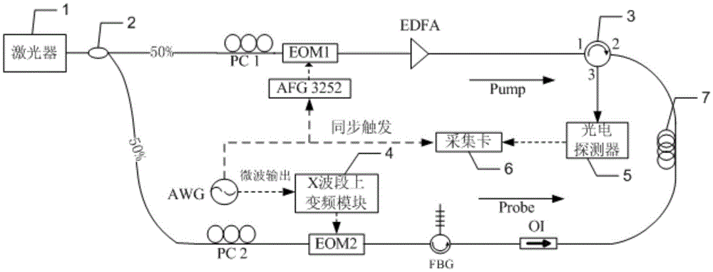
[0030] Specific implementation mode one: the following combination Figure 1 to Figure 4 Describe this embodiment, the real-time dynamic distributed Brillouin fiber sensing device described in this embodiment, it includes a laser 1, a coupler 2, a polarization controller PC1, a polarization controller PC2, an arbitrary function generator AFG3252, an electro-optic modulator EOM1, electro-optical modulator EOM2, arbitrary waveform generator AWG, circulator 3, X-band up-conversion module 4, erbium-doped fiber amplifier EDFA, fiber Bragg grating FBG, optical isolator OI, photodetector 5, acquisition card 6 and waiting Measuring fiber 7;

[0031]The beam output by laser 1 is divided into two laser beams by coupler 2;

[0032] The on-line laser is adjusted to enter the polarization state of the electro-optic modulator EOM1 through the polarization controller PC1, so that the polarization state of the incident electro-optic modulator EOM1 is the same as the polarization state of the...

specific Embodiment approach 2

[0045] Specific embodiment two: the real-time dynamic distributed Brillouin optical fiber sensing method described in this embodiment, the method is realized based on the real-time dynamic distributed Brillouin optical fiber sensing device described in the first embodiment, the method includes the following steps :

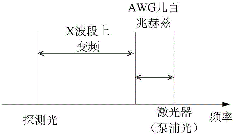
[0046] Step 1. The coupler 2 divides the laser beam into two beams. The upper laser uses step 2 to generate pump light, and the lower laser uses step 3 to generate probe light; both the pump light and the probe light are synchronized by the arbitrary wave generator AWG Completed under control, the arbitrary wave generator AWG sends three control signals, which are the microwave signal of several hundred megahertz for the X-band up-conversion module 4, the trigger signal for the arbitrary function generator AFG3252, and the trigger signal for the acquisition card 6 ;

[0047] Step 2: Adjust the polarization state of the incoming laser light into the electro-optic ...


PUM


Abstract

The invention discloses a real-time dynamic distributed Brillouin fiber sensing device and method, belongs to the field of optics, and aims at solving a problem that a conventional real-time dynamic distributed Brillouin fiber sensing system cannot carry out real-time monitoring. A light beam outputted by a laser is divided by a coupler into two laser beams. An upper laser beam is outputted by any function generator AFG3252 as a square pulse modulation signal for modulation, and then is amplified as pump light. The pump light enters a to-be-detected optical fiber. An X-band up-conversion module is used for carrying out the up and down side-frequency modulation of the lower laser beam. After up and down side-frequency modulation, the lower side frequency of the beam is filtered as detection light through an FBG (Fiber Bragg Grating), and the detection light enters the to-be-detected optical fiber in the other direction. In the to-be-detected optical fiber, the Brillouin amplification of the detection light and pump light meeting the Brillouin amplification condition happens. According to the time of returning to a photoelectric detector, the device and method determine the position of SBS action in the to-be-detected optical fiber, and solves the temperature or strain of different positions at the same time. The device and method achieve the real-time dynamic distributed Brillouin fiber sensing.

Description

technical field [0001] The present invention belongs to the field of optics. Background technique [0002] The invention of optical fiber in the 1960s changed the way of communication in the world. Along with the development of optical fiber communication technology, optical fiber sensing technology developed rapidly. At present, optical fiber sensing technology has been widely used in many fields such as national defense, aerospace, marine exploration, industrial control, energy and environmental protection, civil engineering and construction. [0003] Scattering distributed optical fiber sensing technology is a new type of sensing technology developed in the past 20 to 30 years. Its basic principle is to use optical fiber to sense and transmit signals at the same time, and the Rayleigh, Raman, Brillouin, etc. It can measure the changes of physical quantities such as temperature and strain at different positions along the optical fiber, and realize the real distributed sen...

Claims


Application Information

Patent Timeline
Patent Type & Authority Applications(China)
IPC IPC(8): G01D5/353
CPCG01D5/35364
Inventor 董永康王本章姜桃飞夏猛
Owner ANSHAN REALPHOTONICS TECH CO LTD
Why Eureka
Try Eureka