
Pneumatic optical effect corrector based on self-illuminating wavefront sensor

A wavefront sensor and aero-optics technology, applied in the field of image processing, can solve the problems of low practicability, low wavefront distortion measurement accuracy and accuracy, and poor correction effect of a correction device, and achieves good practicability and accuracy. With high accuracy, the effect of ensuring the correction effect

Active Publication Date: 2016-06-15
INST OF OPTICS & ELECTRONICS - CHINESE ACAD OF SCI
View PDF8 Cites 11 Cited by
  • Summary
  • Abstract
  • Description
  • Claims
  • Application Information

AI Technical Summary

Problems solved by technology

[0005] The inventor found in the research that the measurement of wavefront distortion by the aero-optical effect correction device in the prior art is based on visible light, and aerial photography at night is limited by visible light waves, so that the accuracy and accuracy of wavefront distortion measurement are low. is not high, resulting in poor correction effect and low practicability of the correction device

Method used


Image

  • Pneumatic optical effect corrector based on self-illuminating wavefront sensor
  • Pneumatic optical effect corrector based on self-illuminating wavefront sensor
  • Pneumatic optical effect corrector based on self-illuminating wavefront sensor

Examples


Embodiment Construction

[0045] The following will clearly and completely describe the technical solutions in the embodiments of the present invention with reference to the accompanying drawings in the embodiments of the present invention. Obviously, the described embodiments are only some, not all, embodiments of the present invention. The components of the embodiments of the invention generally described and illustrated in the figures herein may be arranged and designed in a variety of different configurations. Accordingly, the following detailed description of the embodiments of the invention provided in the accompanying drawings is not intended to limit the scope of the claimed invention, but merely represents selected embodiments of the invention. Based on the embodiments of the present invention, all other embodiments obtained by those skilled in the art without making creative efforts belong to the protection scope of the present invention.

[0046] Considering that in the prior art, the aero-o...


PUM


Abstract

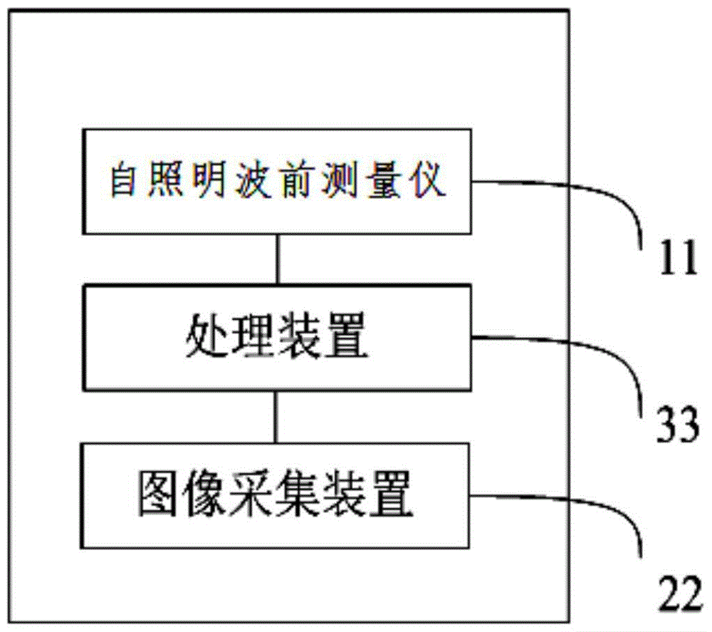
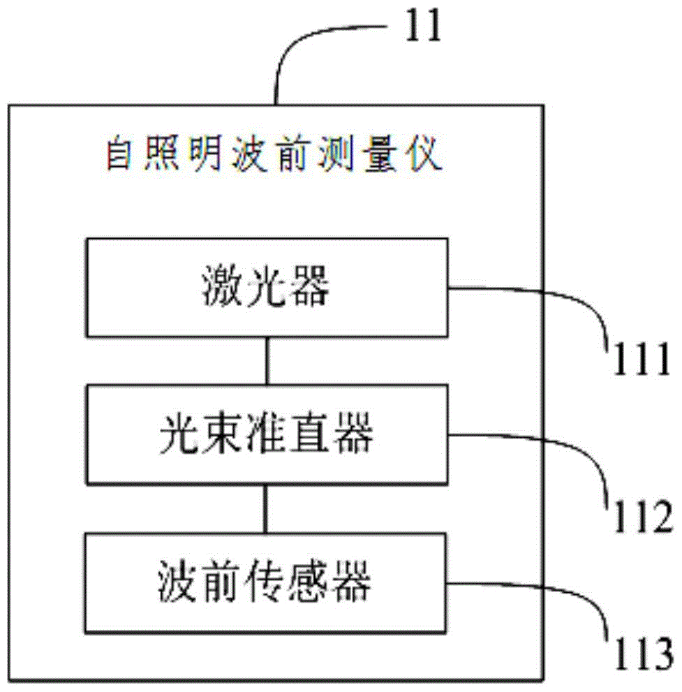
The invention provides a pneumatic optical effect corrector based on a self-illuminating wavefront sensor. The corrector comprises a self-illuminating wavefront measuring instrument, an image collector, and a processor. The self-illuminating wavefront measuring instrument is used to transmit a collimated laser beam, receives a distorted wavefront generated after diffusion light of the collimated laser beam diffused by atmospheric particles is subjected to optical effect, and extracts a deviation parameter of a distorted wavefront. The image collector is used to receive target light wave carrying an original image of a target region and perform image processing of image data of the original image to obtain a real image of the target region. The processor is used for deconvolution operation on the deviation parameter and the real image of the target region to obtain a reconstructed image of the target region. The corrector reconstructs a laser distortion source to effectively measure in real time the wavefront distortion caused by pneumatic optical effect, so that the precision and accuracy of wavefront distortion measurement are both high, and thus good correction effect and practicality of the system are further guaranteed.

Description

technical field [0001] The invention relates to the technical field of image processing, in particular to an aero-optical effect correction device based on a self-illuminating wavefront sensor. Background technique [0002] Aerial images can accurately and comprehensively provide dynamic observation data on a global scale. It is one of the important means of obtaining information in various fields and has very important application value. Aerial images have the advantages of high definition, large scale, small area, and high visibility. Among them, aerial images can be obtained by shooting ground scenes and objects through the high-resolution image acquisition equipment mounted on the aircraft. [0003] However, when the aircraft flies in the atmosphere at high speed, due to the real gas effect between the optical hood and the free flow, the separation of the boundary layer induced by the shock wave, the mutual interference between the inviscid flow and the boundary layer, ...

Claims


Application Information

Patent Timeline
Patent Type & Authority Applications(China)
IPC IPC(8): G01J9/00G06T5/00
CPCG01J9/00G01J2009/002G06T5/00
Inventor 马晓燠樊志华吴建东黄建饶长辉鲜浩饶学军杨金生
Owner INST OF OPTICS & ELECTRONICS - CHINESE ACAD OF SCI
Learn More