
Feed network-based low-frequency compact range feed source

A technology of compact field feed source and feed network, which is applied in the direction of circuits, electrical components, antenna supports/installation devices, etc., which can solve the problems affecting the ease of use of the antenna, the difficulty of installing the feed source, and the large size of the antenna, etc., to achieve irradiation Increased efficiency, mitigation of high impact, and shortened length effects

Active Publication Date: 2016-06-15
BEIHANG UNIV
View PDF4 Cites 5 Cited by
  • Summary
  • Abstract
  • Description
  • Claims
  • Application Information

AI Technical Summary

Problems solved by technology

The original low-frequency feed source has too large axial dimension when the frequency is lower than 500MHz. Typical examples are TEM horn and pyramid four-ridge waveguide horn. This kind of horn antenna generally requires the axial length to be about 1 wavelength of the lowest operating frequency. When working at 300MHz, the length of the antenna reaches nearly one meter, which will make the entire antenna too large in size and heavy in weight, which will inevitably affect the ease of use of the antenna
At the same time, such a feed will be difficult to mount on a feed stand and be compatible with other band feeds

Method used


Image

  • Feed network-based low-frequency compact range feed source
  • Feed network-based low-frequency compact range feed source
  • Feed network-based low-frequency compact range feed source

Examples


Embodiment Construction

[0023] The present invention will be further described below in conjunction with the accompanying drawings and specific embodiments.

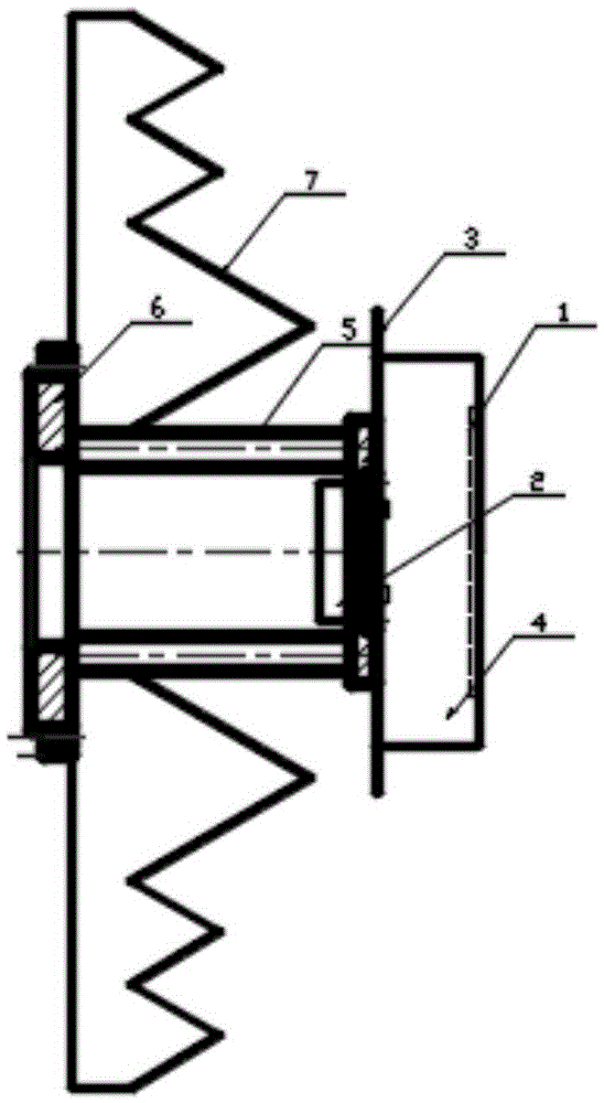
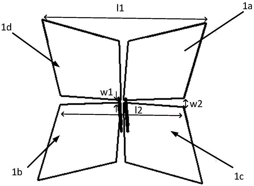
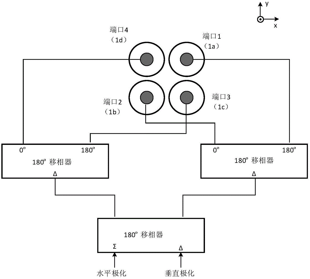
[0024] The idea of ​​the present invention is as follows: the present invention aims at the long problem of the long axial dimension of the traditional feed horn antenna, proposes the scheme that realizes the miniaturization of the feed source with the feed network, adopts ultra-wideband orthogonal dipole antenna 1 as the surface of the ellipse cylinder 4 excitation, the position of the ultra-wideband orthogonal dipole antenna 1 is approximately flush with the position of the elliptical cylinder mouth 4, on the one hand, it ensures that the input impedance of the feed source is close to 50Ω, and on the other hand, it ensures that the radiation pattern close to an elliptical beam. When feeding with two different polarizations, the radiation pattern of the feed horn is approximately the same. The introduction of multiple 180° phase shifters grea...


PUM

PropertyMeasurementUnit
Lengthaaaaaaaaaa

Abstract

The invention relates to a feed network-based low-frequency compact range feed source, which comprises an ultra-broadband orthogonal dipole antenna (1), a feed network (2), a reflective plate (3), an elliptic cylinder opening surface (4), a support structure (5), a flange plate (6) and a wave-absorbing material (7). The feed source constructs a relatively stable feed source radiation pattern by the elliptic opening surface with a specific length-width ratio, and achieves the characteristics of relatively large 3dB beam width of a horizontal direction pattern and relatively small 3dB beam width of a vertical direction pattern on two different incident polarizations. By introducing a broadband feed network, the length of a feed source horn is greatly reduced. Ultra-broadband oscillators are excited through the feed network; and <e>TE<11> and <o>TE<11> modes with higher mode purity are excited. A support post with a certain length is configured behind the horn antenna of the feed source; the opening surface of the horn antenna is far away from a feed source bracket; a wave-absorbing material with a specific size is added to the bottom part of the support post; and multiple radiation caused by a complicated metal structure of the feed source bracket is inhibited. The feed source mainly works at a low frequency; and the specific frequency range is (300MHz-500MHz).

Description

technical field [0001] The invention relates to the technical field of a compact field feed source, in particular to a low-frequency compact field feed source based on a feed network. Background technique [0002] With the continuous development of the compact field technology, the size of the compact field reflective surface is continuously increasing, and the corresponding compact field quiet zone is also continuously increasing. While the compact field technology is progressing, users also hope that the large-aperture compact field reflector can work at low frequencies, so it can measure the antenna and radar cross section from low frequency to the meter wave band. The original low-frequency feed source is too large in the axial direction when the frequency is lower than 500MHz. Typical examples are TEM horns and pyramidal four-ridge waveguide horns. This type of horn antenna generally requires the axial length to be about 1 wavelength of the lowest operating frequency. ...

Claims


Application Information

Patent Timeline
IPC IPC(8): H01Q1/36H01Q1/50H01Q19/10H01Q17/00H01Q15/24H01Q13/02H01Q1/12
CPCH01Q1/12H01Q1/36H01Q1/50H01Q13/02H01Q15/24H01Q17/001H01Q17/008H01Q19/108
Inventor 王正鹏李志平武建华
Owner BEIHANG UNIV
Learn More