Remote optical fibre synchronous system for radio astronomical array and method thereof

A radio astronomy and synchronization system technology, applied in the direction of time division multiplexing system, electrical components, automatic power control, etc., can solve the problems that cannot meet the sampling clock synchronization accuracy requirements of the radio astronomy array, and achieve clock synchronization accuracy High, reduced complexity, low cost effect

Inactive Publication Date: 2016-06-15
SHANGHAI JIAO TONG UNIV
View PDF5 Cites 7 Cited by
  • Summary
  • Abstract
  • Description
  • Claims
  • Application Information

AI Technical Summary

Problems solved by technology

However, the synchronization accuracy achieved by this technology is on the order of tens of picoseconds, which cannot meet the accuracy requirements of the sampling clock synchronization of radio astronomy arrays.

Method used


Image

  • Remote optical fibre synchronous system for radio astronomical array and method thereof
  • Remote optical fibre synchronous system for radio astronomical array and method thereof
  • Remote optical fibre synchronous system for radio astronomical array and method thereof

Examples


Embodiment 1

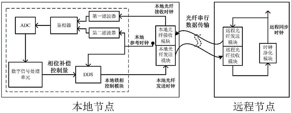
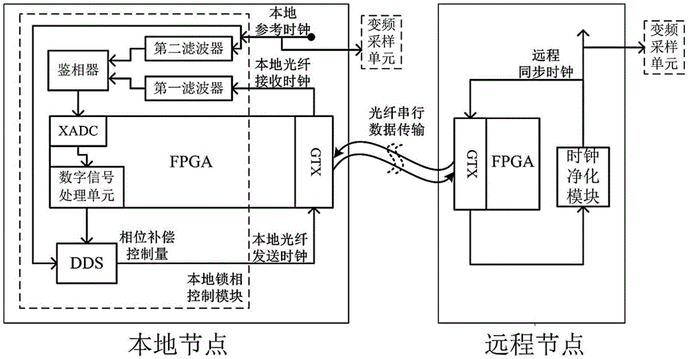
[0027] Such as figure 1 As shown, this embodiment includes: a local phase-locking control module arranged at a local node and a clock purification module arranged at a remote node, wherein: the remote node and the local node are connected through an optical fiber, and the local node connects the local reference clock and the slave clock purification module The received local optical fiber receiving clock is input to the local phase-locking control module, and the phase adjustment of the local reference clock is controlled by PID to obtain the local optical fiber sending clock, thereby realizing optical fiber temperature drift compensation.

[0028] The local phase-locking control module includes: a first filter, a second filter, a phase detector, an analog-to-digital converter (ADC), a digital signal processing unit and a direct digital frequency synthesizer (DDS), wherein: the second The filter, phase detector, ADC, DDS and digital signal processing unit are serially connecte...


PUM


Abstract

The invention relates to a remote optical fibre synchronous system for a radio astronomical array and a method thereof. The remote optical fibre synchronous system comprises a local phase-locked control module and a clock purification module, wherein the local phase-locked control module is arranged in a local node; the clock purification module is arranged in a remote node; the remote node and the local node are connected through an optical fibre; the local node inputs a local reference clock and a local optical fibre receiving clock received from the clock purification module into the local phase-locked control module; the local reference clock is controlled to perform phase adjustment through PID, such that a local optical fibre sending clock is obtained; and thus, optical fibre temperature drift compensation is realized. According to the invention, the optical fibre temperature drift compensation is carried out in a digital manner; the remote optical fibre synchronous system has high clock synchronous precision; the clock synchronous precision is up to the pico-second level; the remote optical fibre synchronous system is high in environment adaptive capability and low in cost; the clock information is transmitted in the digital manner; the remote optical fibre synchronous system is high in anti-interference capability and long in transmission distance; transmission of a sampling clock, sampling data and a system control command can be realized only through one optical fibre channel; therefore, high-degree system integration is realized; and the optical fibre wiring complexity is reduced.

Description

technical field [0001] The invention relates to a technology in the field of distributed antenna arrays of low-frequency radio astronomy telescopes, in particular to a radio astronomy array remote optical fiber synchronization system and a method thereof. Background technique [0002] The object of radio astronomy is the weak electromagnetic signals radiated by celestial bodies in the vast universe. In order to improve the resolution and sensitivity of astronomical observations, it is necessary to continuously increase the antenna aperture of the radio astronomy array. Modern radio astronomy arrays are developing toward large-scale, long-distance, and distributed, which also puts forward higher requirements for the remote clock synchronization performance of radio astronomy arrays. The clock synchronization of modern radio astronomy arrays is mainly used for the sampling clock synchronization of radio astronomy arrays. It needs to achieve extremely high clock synchronizatio...

Claims


Application Information

Patent Timeline
Patent Type & Authority Applications(China)
IPC IPC(8): H04J3/06H03L7/08
CPCH03L7/08H04J3/0638H04J3/0682
Inventor 宫新保秦冕臧小刚
Owner SHANGHAI JIAO TONG UNIV
Why Eureka
Try Eureka