Heat treatment apparatus and heat treatment method

A technology for heat treatment and treatment of containers, used in the manufacture of electrical components, circuits, semiconductor/solid-state devices, etc. The effect of uniformity

Active Publication Date: 2016-06-22
TOKYO ELECTRON LTD
View PDF4 Cites 6 Cited by
  • Summary
  • Abstract
  • Description
  • Claims
  • Application Information

AI Technical Summary

Problems solved by technology

However, when the heating temperature is increased, in addition to the sublimated products sublimated from the crosslinking agent and the like contained in the SOC film, low molecular polymers and the like are also scattered, so the amount of the sublimated products increases.
Therefore, in order to prevent the sublimate fr

Method used


Image

  • Heat treatment apparatus and heat treatment method
  • Heat treatment apparatus and heat treatment method
  • Heat treatment apparatus and heat treatment method

Examples


Example Embodiment

[0101] [Example 1]

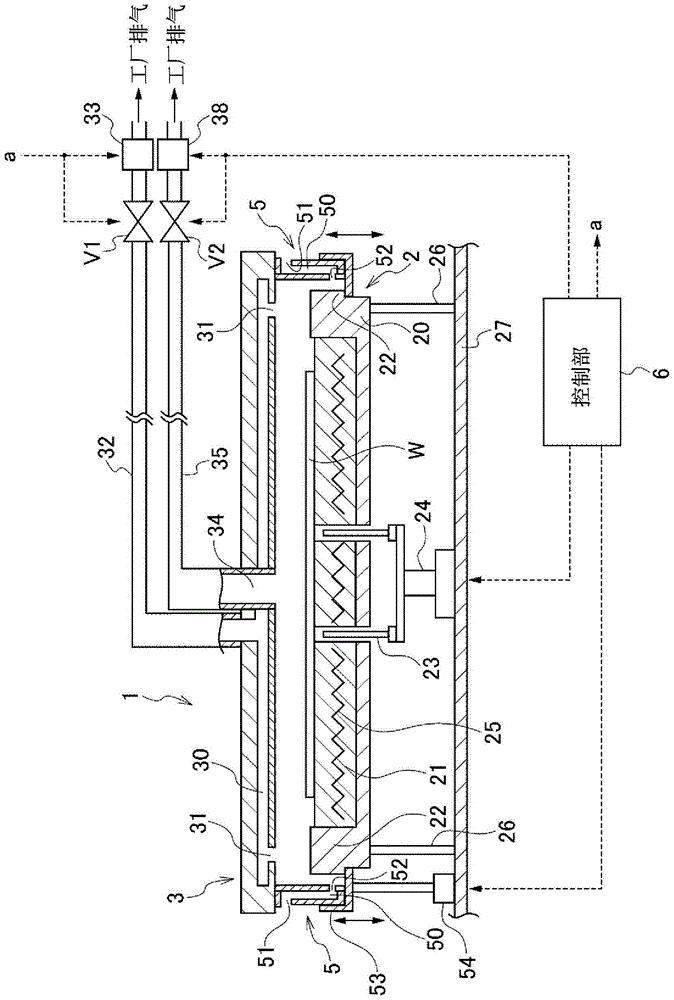
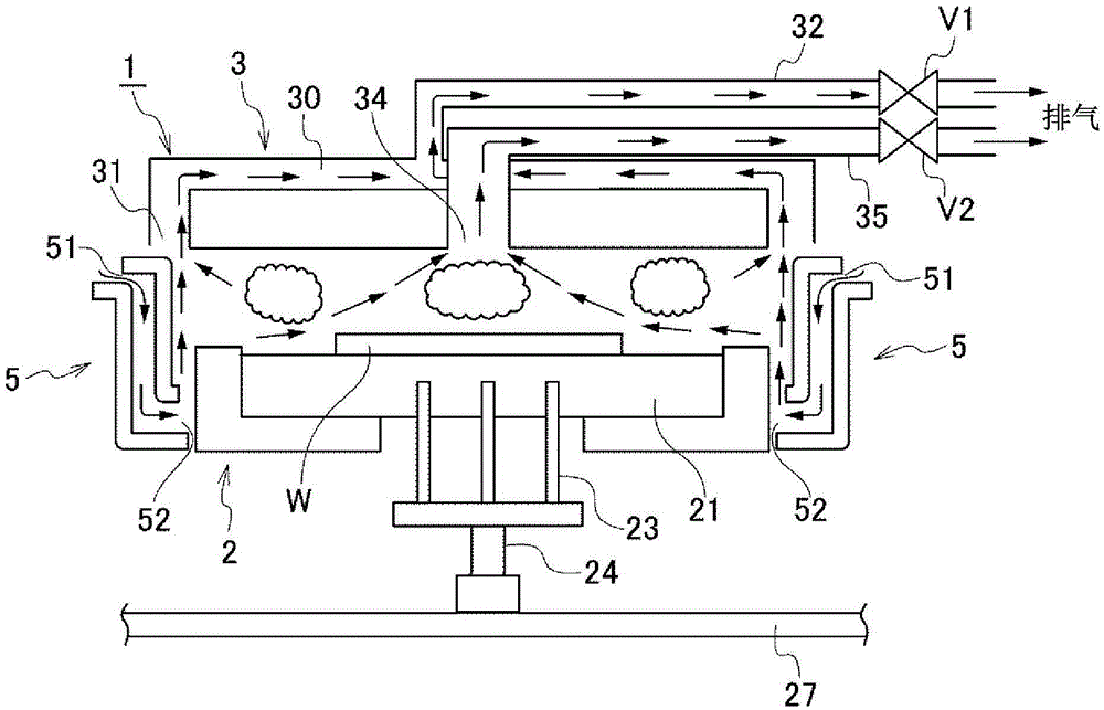
[0102] Examples performed to verify the effects of the embodiments of the present invention will be described. Using the heat treatment apparatus described in the embodiment of the present invention, the wafer W coated with the SOC film was heated to 350°C. Before the wafer W is heat-treated and taken out of the processing chamber 1 , exhaust is performed using the central exhaust port 34 and the peripheral exhaust port 31 , and the number of particles of 100 nm or larger is counted outside the processing chamber 1 . The exhaust flow rate of the central exhaust port 34 and the exhaust volume of the outer peripheral exhaust port 31 in each example were set as follows. In addition, after the wafer W is loaded into the processing container 1 and placed on the bottom structure 2 , heat treatment is performed for 80 seconds, and the ring-shaped opening and closing member 5 is opened to take out the wafer W.

Example

[0103] (Example 1-1)

[0104] The exhaust rate of the outer peripheral exhaust port 31 is set to 20 L / min, and the exhaust rate of the central exhaust port 34 is set to 10 L / min. The period from loading the wafer W into the processing chamber 1 to taking it out , Exhaust is carried out from the outer peripheral exhaust port 31 and the central exhaust port 34.

Example

[0105] (Example 1-2)

[0106] The settings were the same as in Example 1-1 except that the exhaust volume of the outer peripheral exhaust port 31 was set at 25 L / min, and the exhaust volume of the central exhaust port 34 was set at 5 L / min.


PUM


Abstract

The present invention provides a technique in which, in performing a heat treatment on a coating film formed on a substrate, a sublimate is suppressed from leaking out to the outside of a processing container and a good in-plane uniformity with respect to a film thickness of the coating film is obtained. The wafer coated with the SOC film is placed in the processing container (1), the wafer is heated, and the crosslinking reaction proceeds by performing the exhaust from a central exhaust port (34) in a small exhaust amount while performing the exhaust from outer circumferential exhaust ports (31) in a large exhaust amount. In another exemplary embodiment, only the exhaust by the outer circumferential exhaust ports (31) may be performed from the heating start of the wafer, and after 20 seconds from the heating start time, the exhaust from the central exhaust port (34) may be performed in addition to the exhaust from the outer circumferential exhaust ports (31). In another exemplary embodiment, the exhaust is performed only from the outer circumferential exhaust ports (31) for 20 seconds from the heating start time of the wafer, then the exhaust from the outer circumferential exhaust ports (31) is stopped, and the exhaust is performed only from the central exhaust port (34).

Description

technical field [0001] The present invention relates to a heat treatment device, a heat treatment method, and a storage medium for heating the substrate by exhausting the inside of the vessel after placing a substrate coated with a coating liquid in the treatment vessel. Background technique [0002] In semiconductor manufacturing steps, resist patterns tend to collapse due to the refinement of circuit patterns, and various countermeasures have been studied. As one of the countermeasures, a resist pattern is transferred to an underlying film formed on a semiconductor wafer (hereinafter referred to as "wafer"), and the wafer is etched using the pattern of the underlying film as an etching mask. As such an underlayer film, high plasma resistance and high etching resistance are required, and for example, a carbon film (SOC (Spinon Carbon) film) formed by a spin coating method is used. [0003] The wafer coated with the SOC film is heated after the coating process to promote th...

Claims


Application Information

Patent Timeline
IPC IPC(8): H01L21/67H01L21/324
CPCH01L21/324H01L21/3247H01L21/67098
Inventor 水田诚人川路辰也中野圭悟
Owner TOKYO ELECTRON LTD
Why Eureka
Try Eureka