Surface light source device and liquid crystal display device

Active Publication Date: 2016-04-21
MITSUBISHI ELECTRIC CORP
View PDF4 Cites 10 Cited by
  • Summary
  • Abstract
  • Description
  • Claims
  • Application Information

AI Technical Summary

Benefits of technology

[0021]According to the structure of the second surface light source device in accordance with the present invention, the linear light emitted from the light guide rod is reflected and spreads between the reflecting bar

Problems solved by technology

For this reason, if the color purity of the display color is to be increased, there is a problem in that a quantity of light transmitted through the color filter is decreased, resulting in reduction in a luminance.
If the color purity is to be increased in a wavelength region of 630 to 640 nm which is preferable as pure red in the red color, therefore, there is a problem in that the quantity of transmitted light is extremely reduced, resulting in significant reduction in a luminance.
For this reason, a difference is made in the distribution of light illuminating a display surface for every light source so that luminance unevenn

Method used


Image

  • Surface light source device and liquid crystal display device
  • Surface light source device and liquid crystal display device
  • Surface light source device and liquid crystal display device

Examples


first preferred embodiment

A-1. Structure

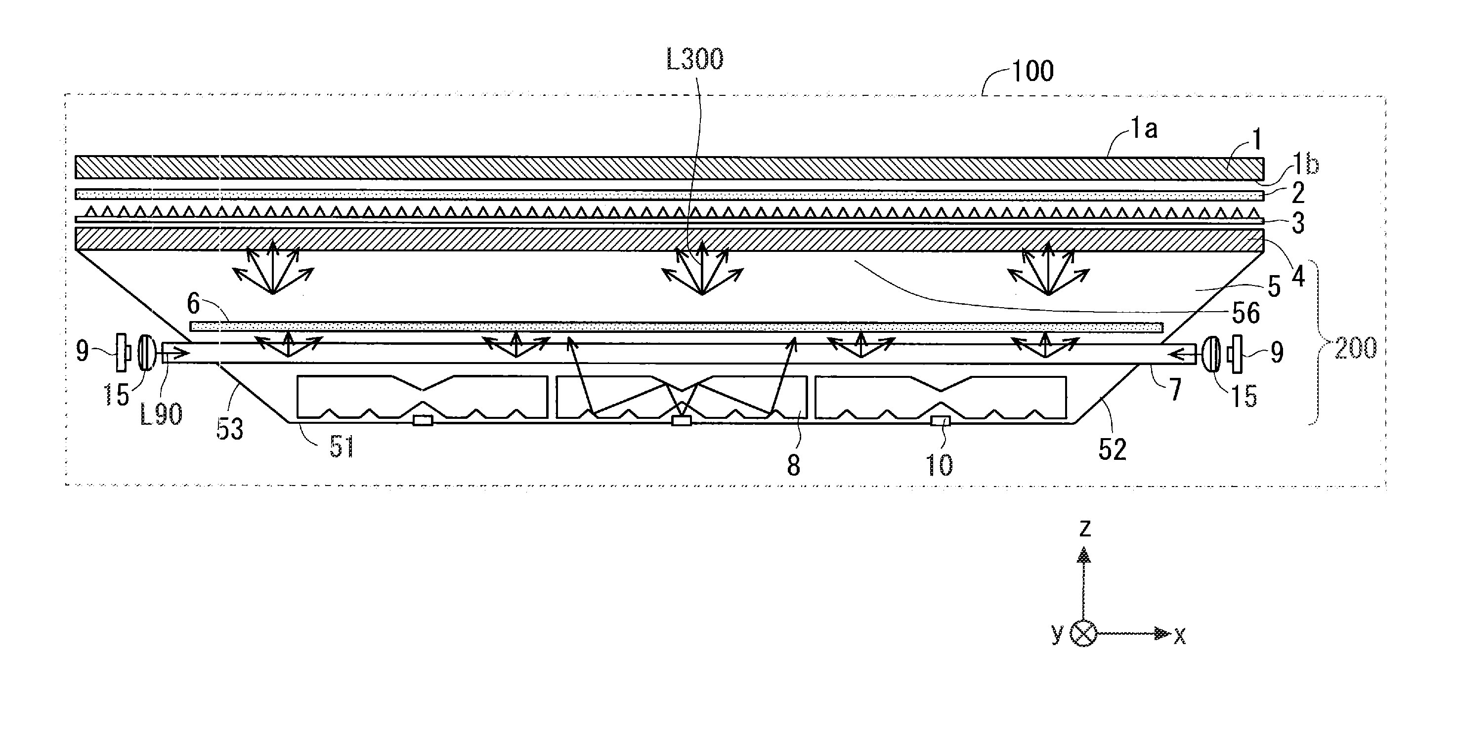
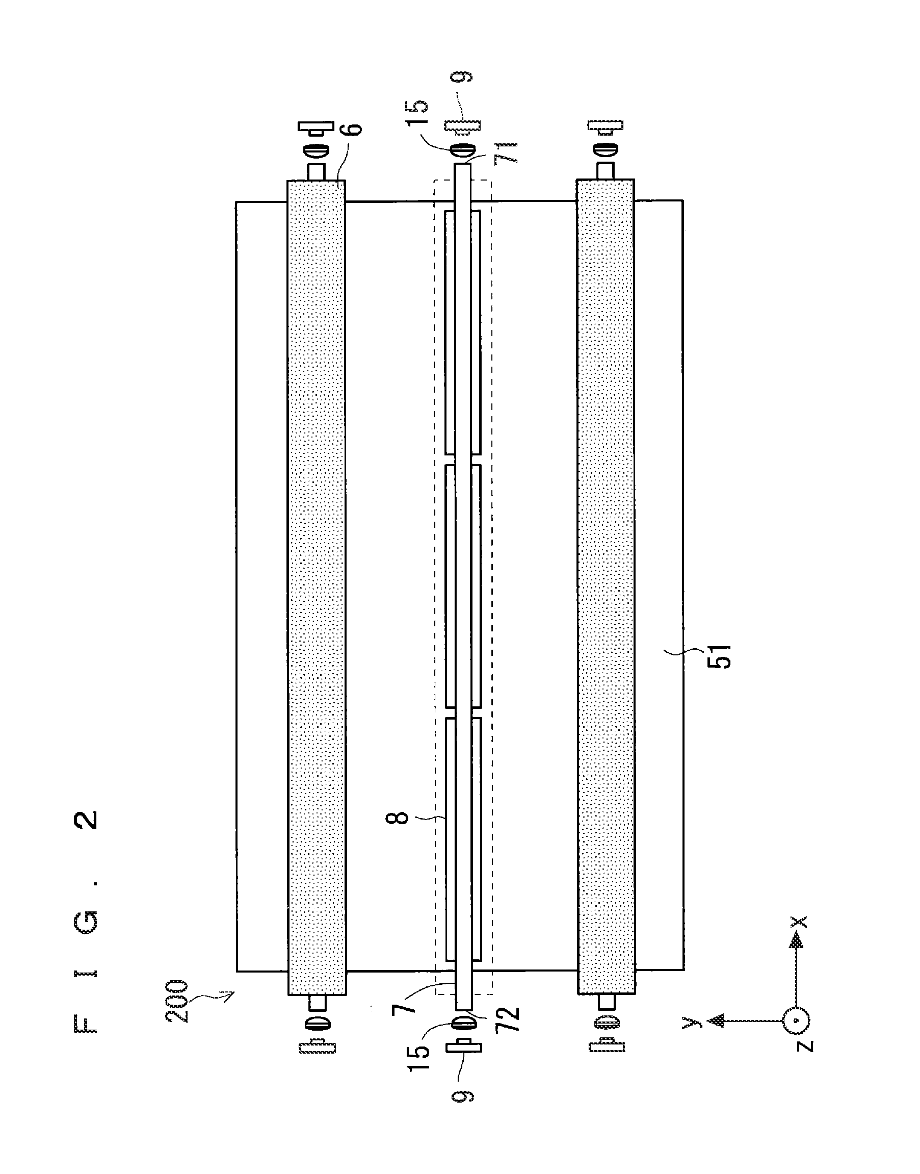
[0032]FIGS. 1 and 3 show a structure of a liquid crystal display device 100 according to a first preferred embodiment. FIG. 1 is a view showing the liquid crystal display device 100 seen in one direction, and FIG. 3 is a view showing the liquid crystal display device 100 seen in a different direction from the direction in FIG. 1. FIG. 2 shows a structure of a surface light source device 200 to be a component of the liquid crystal display device 100.

[0033]As shown in FIG. 1, the liquid crystal display device 100 includes a transmission type liquid crystal panel 1 formed by a liquid crystal display element, optical sheets 2 and 3, and a surface light source device 200.

[0034]FIG. 5 is a functional block diagram showing the liquid crystal display device 100. As shown in FIG. 5, the liquid crystal display device 100 further includes a control unit 31, a liquid crystal panel driving unit 32, an LED light source driving unit 33a, and a laser beam source driving unit 33b. Thes...

modification example

A-4. Modification Example

[0085]FIG. 6 is a view showing a structure of a surface light source device 201 according to a first modification example of the present preferred embodiment. In the surface light source device 200 shown in FIGS. 1 and 2, the lens 15 is disposed opposite to each of the incident surfaces 71 and 72 of the laser beam guide rod 7. In contrast, in the surface light source device 201, the lens 15 is disposed between the incident surface 72 of the laser beam guide rod 7 and the laser beam source 9, and is not disposed on an incident surface 71 side, and output light of the laser beam source 9 is directly incident on the incident surface 71. In this case, an interval between the incident surface 71 and the laser beam source 9 is fixed so as not to be varied depending on temperature and humidity, and they are thus disposed close to each other. On the other hand, the incident surface 72 side including the lens 15 has such a structure as to enable change in a length of...


PUM


Abstract

A surface light source device includes a first light source for emitting first light, a first light guide rod for causing the first light to be incident thereon and converting the first light into first linear light, a second light source for emitting second light having a greater divergence angle than the first light, and a second light guide rod for converting the second light into second linear light extended in the same direction as the first linear light. Moreover, the surface light source device includes a reflecting bar disposed on an emitting side of the planar light from the first and second light guide rods, and a reflecting portion taking such a box shape as to have an internal wall serving as a reflecting surface, and having an opening portion on a surface at the emitting side of the planar light.

Description

BACKGROUND OF THE INVENTION[0001]1. Field of the Invention[0002]The present invention relates to a technique for enhancing in-plane uniformity of a surface light source device.[0003]2. Description of the Background Art[0004]A liquid crystal display element provided in a liquid crystal display device does not emit light by itself. For this reason, the liquid crystal display device includes a backlight device (a surface light source device) as a light source for illuminating the liquid crystal display element at a back surface side of the liquid crystal display element.[0005]Moreover, the liquid crystal display element includes a color filter and transmits, through a color filter, only light having a part of wavelengths in light emitted from a fluorescent lamp for emitting white light in a continuous spectrum, thereby extracting display colors of red, green and blue to perform color representation. In the case in which only light in a part of wavelength bands is cut out of light sourc...

Claims


Application Information

Patent Timeline
IPC IPC(8): F21V8/00
CPCG02B6/0006G02B6/001G02B6/0031G02F1/133605G02F1/133615G02F1/133607G02B6/0051G02B6/0078G02F1/133603G02F1/133606G02F1/133612G02F1/133613G02F1/133624
Inventor KIDA, HIROSHIDAIJOGO, AKIRAMAEDA, SAKIOKIMOTO, NAMINIIKURA, EIJI
Owner MITSUBISHI ELECTRIC CORP
Why Eureka
Try Eureka