Adjustable tray lifting device used for automatic stock bin

A lifting device and pallet technology, which is applied in metal processing and other directions, can solve the problems of difficult position accuracy control, low positioning accuracy, and tolerance, and achieve the effects of accurate positioning position, wide application range, and reduced production costs

Active Publication Date: 2016-06-29
NINGXIA KOCEL MACHINE TOOL ACCESSORIES
11 Cites 13 Cited by

AI-Extracted Technical Summary

Problems solved by technology

[0003] In production, the size of the workpieces produced will be different, which requires adjustment of the storage station to meet workpieces of different sizes. Pallet silos, such as 16-station turntable silos and 20-station turntable silos, have the following main problems: ①The positioning accuracy of the processed parts on the pallet in the silo is low, so It will cause the loading and unloading manipulator in the process of loading and unloading, it may not catch the processed parts or touch the processed parts, so that the production line cannot be used normally; ② When the processed parts change, the feed bin The trays placed in the center need to be replaced, so a large number of trays need to be prepared to meet the needs of processing parts of different sizes;
[0004] ③The structure of the storage station is compl...

Abstract

The invention relates to an adjustable tray lifting device used for an automatic stock bin. The adjustable tray lifting device mainly comprises a workpiece clamping mechanism, a tray positioning mechanism and a tray lifting mechanism. The workpiece clamping mechanism adopts a three-rod-guided adjustable tray clamping technology. The tray positioning mechanism comprises needle bearing installation bases, needle bearings, an upper supporting base, a lower supporting base, a cylinder, an ejector head, a cylinder flange and a profiling block. The tray lifting mechanism comprises bottom plates, ejector polished shafts, linear bearings, a polished shaft upper fixing plate, ball screw nuts, a polished shaft lower fixing plate, ball screws, motors, bearing blocks, angular contact ball bearings, deep groove ball bearings and proximity switch supports. The bottom plates, the polished shaft upper fixing plate and the proximity switch supports vertically installed on the bottom plates are fixed through bolts, and fixation relative to the bottom plates is maintained. The adjustable tray lifting device has the advantages that the problem that use functions are affected due to large workpiece accumulative errors is effectively solved, production cost is reduced, high-efficiency energy conservation is achieved, the positioning position is precise, and the application range is wide.

Application Domain

Technology Topic

Needle roller bearingOptical axis +4

Image

  • Adjustable tray lifting device used for automatic stock bin
  • Adjustable tray lifting device used for automatic stock bin
  • Adjustable tray lifting device used for automatic stock bin

Examples

  • Experimental program(1)

Example Embodiment

[0021] specific implementation
[0022] Attached below Figure 1-7 The present invention is further analyzed.
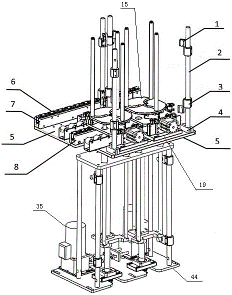
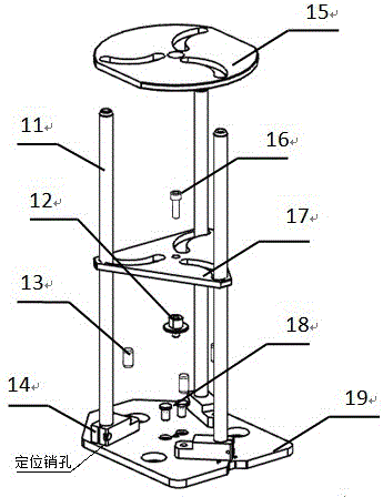
[0023] like Figure 1-2 As shown in the figure, the adjustable pallet lifting device for automatic silo of the present invention mainly includes three parts: a workpiece clamping mechanism, a pallet positioning mechanism and a pallet lifting mechanism; the workpiece clamping mechanism is as follows: image 3 Shown: using three-bar guide adjustable pallet clamping technology, the pallet includes two pins 18 connected to the bottom plate 19, the lower ends of the pins 18 are connected with the attachment plate holes on the chain, the The chain drives the bottom plate 19 to realize operation through the pin shaft; the bottom plate 19 is fixed with a nut 12, and three positioning pin holes and three cylindrical pins 13 are evenly distributed on a circle whose center is the center of the nut 12. A rotatable support rod fixing adjustment seat 14 is installed on the hole, a guide rod 11 is arranged on the support rod fixing adjustment seat 14, and the lifting tray 15 and the adjustment support plate 17 are sleeved on the guide rod 11 from top to bottom, The adjustment support plate 17 is fixed on the bottom plate 19 by the bolts 16 matched with the fixed shaft seat; the lifting support plate 15 and the adjustment support plate 17 are evenly distributed with semi-circular arc grooves with positioning holes;
[0024] like Figure 4-5 As shown, the pallet positioning mechanism includes a needle roller bearing mounting seat 20, a needle roller bearing 21, an upper support 22, a lower support 24, a cylinder 25, a plug 26, a cylinder flange 27 and a profiling block 28, so One end of the upper support 22 and the lower support 24 are respectively installed on the rack mounting plate 5, the other ends of the upper support 22 and the lower support 24 are fixedly installed on the side of the bottom plate 19, and the rack mounting plate 5 is installed on the There is a metal chip wheel frame 7, the inside of the metal chip wheel frame is provided with a conveyor chain slideway 8, the metal chip wheel frame 7 is installed with metal chip wheels 6 at equal intervals, and a conveyor chain is installed on the metal chip wheel 6 10. The bottom plate 19 is supported on the metal chip wheel 6, the needle roller bearing mounting seat 20 is fixedly mounted on the upper support 22, the needle roller bearing mounting seat 20 is mounted on the needle roller bearing 21, and the cylinder 25 passes through the cylinder The flange 27 is installed on the lower support 24, the plug 26 is installed in the middle of the lower support 24, and a profiling block 28 is arranged between the plug 26 and the cylinder flange 27;
[0025] like Figure 6-7Shown: the tray lifting mechanism includes a bottom plate II 44, a lifting optical axis 29, a linear bearing 30, a fixed plate 31 on the optical axis, a ball screw nut 32, a lower fixed plate 33 on the optical axis, a ball screw 34, and a motor 35 , bearing seat 36, angular contact ball bearing 37, deep groove ball bearing 38 and proximity switch bracket 39, the bottom plate II44, the fixing plate 31 on the optical axis and the proximity switch bracket 39 vertically installed on the bottom plate II44 are fixed by bolts Keep the position fixed with the bottom plate II44, the lower fixing plate 33 of the optical axis and the motor mounting plate 23 are fixed on the bottom plate II44 by bolts, and the motor 35 and the bearing seat 36 are fixed relative to the bottom plate II44 by bolts, the said The lower end of the ball screw 34 is fixed by the bearing seat 36 on which the angular contact ball bearing 37 is installed, and the upper end is fixed by the deep groove ball bearing 38 installed on the fixing plate 31 on the optical axis. The lower fixing plate 33 of the optical axis is fixed by bolts and balls The ball screw nut 32 on the screw rod 34 is connected. The ball screw nut 32 is evenly distributed with the ball screw nut 32 as the center to install three lifting optical shafts 29. Fixed on the fixed plate 33 under the optical axis, the upper end of the lifting optical axis 29 is matched with the linear bearing 30 installed on the fixed plate 31 on the optical axis, and one end of the output shaft of the motor 35 is input with the ball screw 34 A synchronous pulley 43 with a speed ratio of 1:1 is installed on each end, a synchronous belt 42 is installed on the synchronous pulley 43, a proximity switch mounting seat 40 is arranged on the proximity switch bracket 39, and the proximity switch The mounting base 40 is provided with an upper and lower proximity switch 41, the proximity switch 41 feeds back a signal to the PLC to control the motor 35, and the proximity switch 41 respectively controls the upper and lower limit positions of the ball screw 34;
[0026] like figure 1 and 2 As shown, the rack mounting plate 5 is provided with a fire switch bracket 4, the fire switch bracket 4 is provided with a fire switch bracket 2, and the fire switch bracket 2 is respectively provided with There are an on-fire switch mounting seat 3 and a on-fire switch mounting plate 1, and on the illustrated on-fire switch mounting seat 3 a on-fire switch 9 is arranged.
[0027] The specific structure of the present invention is further introduced below, and the present invention can be decomposed into three functional modules:
[0028] (1) Workpiece clamping mechanism; (2) Pallet lifting mechanism; (3) Pallet positioning mechanism;
[0029] Regarding the workpiece holding mechanism, the solution we adopted is: a three-bar guide adjustable pallet clamping solution. The pallet includes two pin shafts 18 connected to the bottom plate 19I. The lower end of the pin shafts 18 is connected with the attachment plate hole on the chain. The running chain drives the bottom plate I19 to realize the operation through the pin shaft. The guide rod 11 and the lifting tray 15 installed on the bottom plate I19 are characterized in that a nut 12 is fixed on the bottom plate I19, and the center of the nut 12 on the bottom plate I19 is evenly distributed on the circle with the center of the circle. A rotatable strut fixing adjustment seat 14 is installed on the positioning pin, a guide rod 11 is arranged on each strut fixing adjustment seat 14, and positioning holes are evenly distributed on the lifting bracket 15 and the adjustment bracket 17. Semi-circular arc groove, the radius of the semi-circular arc groove is the center distance between the pin on the rotatable support rod fixing adjustment seat 14 and the guide rod 11 which can be fixed on the support rod fixing seat 14, the lifting tray 15 and the adjustment bracket The plate 17 is sleeved on the guide rod 11 from top to bottom, and the adjusting support plate 17 is fixed on the bottom plate I19 by the bolts 16 matched with the fixed shaft seat. Each time the workpiece is clamped, the loosening bolt 16 is rotated and the adjustment tray 17 is adjusted to adjust the guide rod 44 to slide in the semi-circular arc groove of the lifting tray 15 to realize clamping workpieces of different sizes.
[0030] Regarding the pallet lifting mechanism, the solution we adopted is: the base plate II44 installed on the silo rack, the fixing plate 31 on the optical axis and the proximity switch bracket 39 vertically installed on the base plate II44 are fixed by bolts to keep the position of the base plate II44 fixed. , the lower fixing plate 33 of the optical axis and the motor mounting plate 23 are fixed on the base plate II 44 by bolts, the motor 35 and the bearing seat 36 are fixed relative to the base plate II 44 by bolts, and the lower end of the ball screw 34 is installed with an angular contact ball bearing 37 The bearing seat 36 and the upper end are fixed by the deep groove ball bearing 46 installed on the fixing plate 31 on the optical axis, and the lower fixing plate 33 on the optical axis is connected with the ball screw nut 32 on the ball screw 34 by bolts. The rod nut 32 is the center, and three lifting optical shafts 29 are installed evenly. match. A synchronous pulley 43 with a speed ratio of 1:1 is installed at one end of the output shaft of the motor 35 and the input end of the ball screw 34. The upper and lower proximity switches 41 on the proximity switch bracket 39 are fed back to the PLC through signals, and the PLC controls the motor, thereby realizing optical The lifting position of the fixing plate 33 under the shaft. The proximity switches 41 at the upper and lower stations respectively control the upper and lower limit positions of the ball screw 34 to prevent the motor 35 from being overloaded.
[0031] Regarding the pallet positioning mechanism, the solution we adopted is: the metal chip wheel frame 7 installed on the rack mounting plate 5, the metal chip wheel 6 is installed at equal intervals, the bottom plate I19 is supported on the metal chip wheel 6, the upper support 22, the lower The supports 24 are respectively installed on the rack mounting plate 5, the needle roller bearing 21 is mounted on the needle roller bearing mounting seat 20, the needle roller bearing mounting seat 20 is fixed on the rack mounting plate 5, and the cylinder 25 is installed on the bottom through the cylinder flange 27. on the bracket 24. At this time, the frame mounting plate 5 is a finishing thick plate, which ensures that the metal chip wheel frame 7, the upper support 22, and the lower support 24 are on the same reference plane at the same time. When the lifting optical axis 29 lifts the lifting pallet 15, the needle roller bearing 21 can ensure that the bottom plate I19 is always kept horizontal, preventing the lifting pallet 15 from rising to the grasping position of the manipulator due to the inaccurate position of the bottom plate I19. The material feeding of the mechanism is not accurate, which affects the cooperation with the manipulator. When the bottom plate I19 is dragged to the ascending and descending stations by the chain assembled in the conveyor chain slideway 8, the cylinder 25 gives a horizontal force to the jack 26 through the profiling block 28, and the gap between the jack 26 and one end of the bottom plate I19 passes through the gap Cooperate with the base plate I19 to complete the secondary precise positioning.
[0032] The description of the above embodiment is only used to help understand the method of the present application and its core idea; meanwhile, for those of ordinary skill in the art, according to the idea of ​​the present application, there will be changes in the specific embodiment and the scope of application, In conclusion, the content of this specification should not be construed as a limitation on the present application.

PUM

no PUM

Description & Claims & Application Information

We can also present the details of the Description, Claims and Application information to help users get a comprehensive understanding of the technical details of the patent, such as background art, summary of invention, brief description of drawings, description of embodiments, and other original content. On the other hand, users can also determine the specific scope of protection of the technology through the list of claims; as well as understand the changes in the life cycle of the technology with the presentation of the patent timeline. Login to view more.

Similar technology patents

Self-venting valve end cap and method

ActiveUS6972092B1Reduce manufacturing costImproves filter reliability and wear characteristicCombination devicesAuxillary pretreatmentEngineeringDiesel engine
Owner:WIX FILTRATION

Classification and recommendation of technical efficacy words

  • Reduce manufacturing cost
  • Accurate location

Indoor location identification system

InactiveUS20050143091A1Accurate locationEmergency connection handlingConnection managementSTI OutpatientSystem definition
Owner:CORNING MOBILEACCESS
Why Eureka
Try Eureka