Plant drying and essential oil and hydrolat extraction system based on air energy

An extraction system and air energy technology, applied in the direction of biomass drying, dry solid materials, essential oils/fragrances, etc., can solve the problems of high equipment manufacturing costs, lower product quality, complex equipment structure, etc., to achieve convenient operation and maintenance, improve The effect of high product quality and equipment integration

Pending Publication Date: 2016-06-29
上海依肯机械设备有限公司
9 Cites 15 Cited by

AI-Extracted Technical Summary

Problems solved by technology

[0004] In this method, the temperature exceeds 100°C due to the vaporization of water, and the aroma raw materials will react at high temperature. Usually, the aroma of essential oils and hydrosols and the aroma of the plant itself are quite different, which reduces the quality of the product.
In addition, because the heating equipment 2 generally adopts boilers or electric heating equipment, the equipment system is complicated, and the boilers, water towers and other equipment occupy a large area, consume high energy consumption, and the equipment manufacturing cost is also high, and the exhaust gas discharge pollutes the environment
Electric heating equipment also has the problem of high energy consumption
In addition, after the extraction of essential oils and hydrosols, the remaining plant fragrance materials ...

Abstract

The invention relates to a plant drying and essential oil and hydrolat extraction system based on air energy.The plant drying and essential oil and hydrolat extraction system comprises a drying oven, a condenser, an oil-water separator and an air energy heating and cooling unit.The drying oven is used for drying plants and volatilizing moisture and essential oil in the plants to form oil-water gaseous state mixture.The condenser is connected with the drying oven and used for lowering the temperature of the gaseous state mixture and converting the gaseous state mixture into liquid state mixture.The oil-water separator is used for separating the liquid state mixture into essential oil and hydrolat.The air energy heating and cooling unit heats the drying oven and cools the condenser.Compared with the prior art, the system improves device production efficiency and greatly lowers device energy consumption; due to high system integration, the device site requirements are lowered, the device structure is simplified, the device investment is lowered, the device operation difficulty and maintenance cost are lowered, and environmental pollution caused by exhaust emission is avoided.

Application Domain

Technology Topic

Oil–water separatorOil water +12

Image

  • Plant drying and essential oil and hydrolat extraction system based on air energy
  • Plant drying and essential oil and hydrolat extraction system based on air energy
  • Plant drying and essential oil and hydrolat extraction system based on air energy

Examples

  • Experimental program(1)

Example Embodiment

[0035] Example
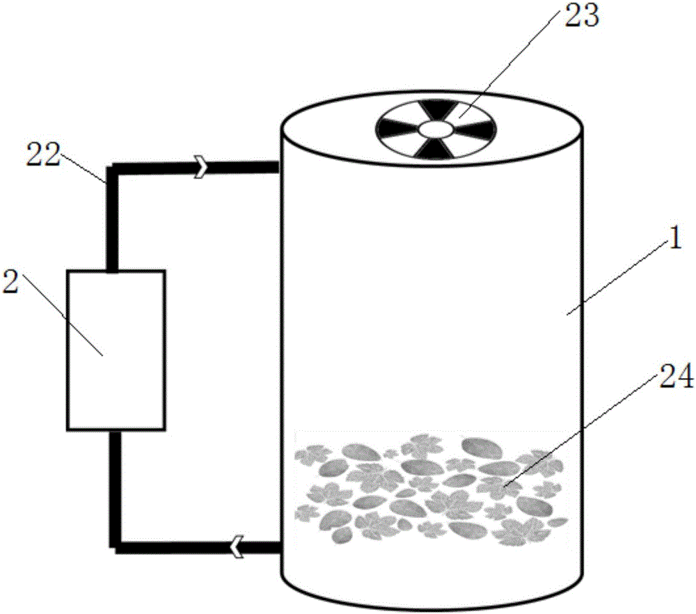
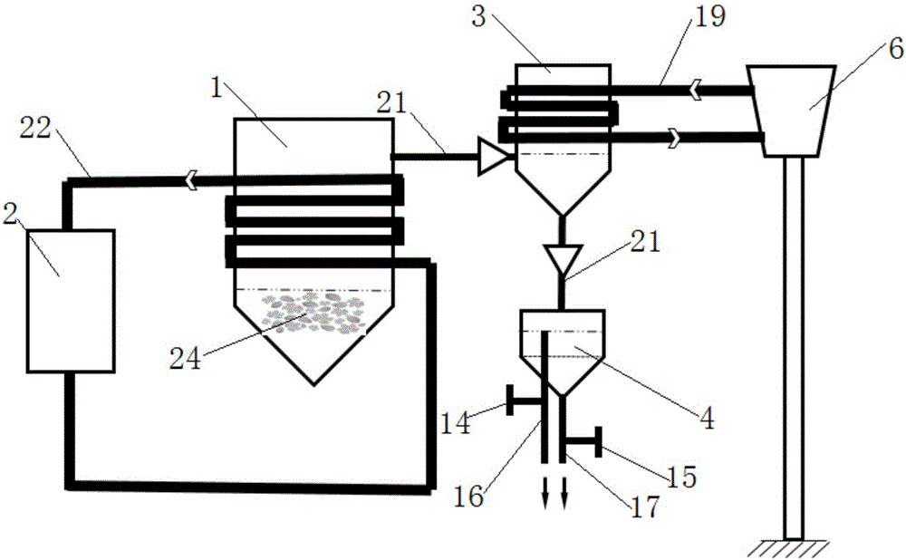
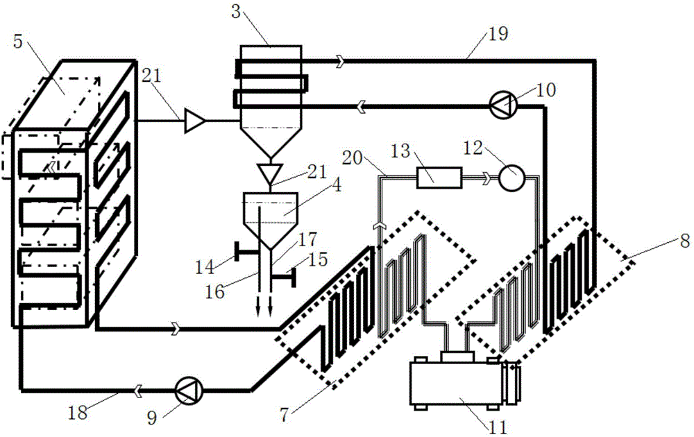
[0036] A plant drying and essential oil and dew extraction system based on air energy, such as image 3 As shown, it includes a plant drying unit, an essential oil, a pure dew extraction unit, and an air energy heating and cooling unit. The plant drying unit is a drying box 5, which is used to dry plants and vaporize water and essential oils in the plants to form a gaseous mixture of oil and water; The essential oil and pure dew extraction unit includes a connected condenser 3 and an oil-water separator 4. The condenser 3 is connected with a drying box 5 to reduce the temperature of the gaseous mixture into a liquid state, and the oil-water separator 4 is used to separate the liquid mixture into Essential oil and pure dew; the air energy heating and cooling unit includes a first heat exchanger 7, a second heat exchanger 8 and a refrigerant circuit; the first heat exchanger 7 includes a heating water pipe 18 and a refrigerant heat exchange pipe that exchange heat, The heating water pipe 18 communicates with the heat exchange coil on the drying box 5 and supplies heat to the drying box 5; the second heat exchanger 8 includes a cooling water pipe 19 and a refrigerant heat exchange pipe that exchange heat with each other, and a cooling water pipe 19 and a condenser 3 The heat exchange coil is connected to provide cooling to the condenser 3; the refrigerant circuit consists of the refrigerant heat exchange tube in the first heat exchanger 7, the refrigerant heat exchange tube in the second heat exchanger 8, and the refrigerant pipeline 20 and the compressor 11 are connected to form a circulation circuit for refrigerant circulation, and a refrigerant expansion valve 12 and a refrigerant storage tank 13 are provided on the refrigerant pipe 20.
[0037] Specifically, one end of the compressor 11 is connected to one end of the refrigerant heat exchange tube in the first heat exchanger 7, and the other end of the compressor 11 is connected to one end of the refrigerant heat exchange tube in the second heat exchanger 8. The other end of the refrigerant heat exchange tube in the first heat exchanger 7 and the other end of the refrigerant heat exchange tube in the second heat exchanger 8 are connected by a refrigerant pipeline 20.
[0038] Along the direction from the refrigerant heat exchange tube in the first heat exchanger 7 to the refrigerant heat exchange tube in the second heat exchanger 8, the refrigerant flows through the refrigerant storage tank 13 and the refrigerant expansion valve 12 in sequence. The heating water pipe 18 is provided with a first circulating water pump 9. The cooling water pipe 19 is provided with a second circulating water pump 10. The oil-water separator 4 is provided with an essential oil discharge pipe 16 for discharging lighter essential oils and a dew discharge pipe 17 for discharging heavier dew. A first valve 14 is provided on the essential oil discharge pipe 16, and the A second valve 15 is provided on the dew discharge pipe 17. The drying box 5 is a multi-layer vacuum drying box. The condenser 3 is a vacuum condenser.
[0039] It also includes a vacuum device for vacuuming the drying box 5, the condenser 3, or the pipes connected to the two.
[0040] When the system of the present invention is used, plants such as fragrant raw materials are placed in the drying box 5. After the system of the present invention is closed, the air is automatically exhausted to make the system work in a vacuum environment. The temperature of plants such as fragrance materials increases in a vacuum environment, and moisture and essential oils can be volatilized and separated from plants at a lower temperature. Plants such as fragrance materials are dried, and the volatile water and essential oils enter the condenser 3 through the extraction pipeline 21. . The mixture of moisture and essential oil is exchanged for heat in the condenser 3, and the moisture and essential oil change from gas to liquid, and enter the oil-water separator 4. Essential oil and water will have a difference in liquid level due to the difference in density. The lighter essential oil is discharged through the essential oil discharge pipe 16, and the heavier dew is discharged through the dew discharge pipe 17. The first valve 14 is set on the essential oil discharge pipe 16. A second valve 15 is provided on the dew discharge pipe 17.
[0041] The heat exchange process between the first heat exchanger 7 and the second heat exchanger 8 is as follows: the compressor 11 converts the refrigerant in the refrigerant circuit from a low temperature and low pressure gas state to a high temperature and high pressure gas state. Due to the temperature difference, the first heat exchange The device 7 exchanges heat with the water in the heating water pipe 18, and the heated water passes through the first circulating water pump 9 to deliver hot water to the heat exchange coil of the drying box 5 to heat the drying box 5. At the same time, the high-temperature and high-pressure gas in the refrigerant circuit is converted into a low-temperature and high-pressure gas, and a low-temperature and high-pressure gas and a low-temperature and high-pressure liquid coexist in the refrigerant storage tank 13 for gas-liquid separation. The low-temperature and high-pressure liquid passes through the refrigerant expansion valve 12 and is converted into a low-temperature and low-pressure liquid state. The water in the second heat exchanger 8 and the cooling water pipe 19 exchange heat under the temperature difference, and the cooled water passes through the second circulating water pump 10 to deliver the cold water. To the condenser 3, it plays a role of cooling the solvent. At the same time, the refrigerant absorbs heat into a low-temperature and low-pressure gas state, and returns to the compressor 11 for the next cycle.

PUM

no PUM

Description & Claims & Application Information

We can also present the details of the Description, Claims and Application information to help users get a comprehensive understanding of the technical details of the patent, such as background art, summary of invention, brief description of drawings, description of embodiments, and other original content. On the other hand, users can also determine the specific scope of protection of the technology through the list of claims; as well as understand the changes in the life cycle of the technology with the presentation of the patent timeline. Login to view more.

Similar technology patents

Child protective wall

PendingCN107338923AIncrease product valueEasy to connectCovering/liningsFlooringFunctional monomerPackage design
Owner:ZHEJIANG SCI-TECH UNIV

Method for synchronously separating potassium, lead and iron in sintering machine head ash

ActiveCN113088709AReduce leaching and filtration processIncrease product valueProcess efficiency improvementGravity separationLeaching rate
Owner:PANZHIHUA IRON & STEEL RES INST OF PANGANG GROUP

Water tank anti-freezing solution

InactiveCN106634870AReasonable selection of raw materialsIncrease product valueHeat-exchange elementsIonChemistry
Owner:WUHU LEPU AUTOMOTIVE TECH CO LTD

Biological compound fertilizer

InactiveCN107056427AIncrease product valueNatural long shelf lifeExcrement fertilisersBioloigcal waste fertilisersChitinPeat
Owner:黄少娟

Manufacturing method of leather with 3D effect

InactiveCN111318433AIncrease product valueLiquid surface applicatorsLeather surface mechanical treatmentComposite materialManufacturing engineering
Owner:ZHEJIANG MINGXIN XUTENG LEATHER IND CO LTD

Classification and recommendation of technical efficacy words

  • Good quality
  • Increase product value

Clock multiplier

ActiveUS6977536B2Good qualityContinuous to patterned pulse manipulationOscillations generatorsEngineeringAudio power amplifier
Owner:INTEGRATED SILICON SOLUTION

Burdock color-protecting crisp-keeping mixed preparation and using method thereof

InactiveCN103141566AGood sensory qualityIncrease product valueFruit and vegetables preservationPre treatmentChemistry
Owner:NANJING AGRICULTURAL UNIVERSITY

Clean separation method for bastnaesite (bastnasite)

InactiveCN102399975AIncrease product valueProcess efficiency improvementActive agentCerium fluoride
Owner:周毅

Antenna combination device and mobile terminal

ActiveCN110086552AIncrease product valueLow costTransmission monitoringVIT signalsRadio frequency circuits
Owner:ONEPLUS TECH SHENZHEN

System and method for preparing titanium carbide from vanadium titano-magnetite comprehensively

PendingCN107653353AIncrease product valueEnvironmentally friendlyTitanium carbideShaft furnaceExhaust gasTitanium carbide
Owner:JIANGSU PROVINCE METALLURGICAL DESIGN INST
Why Eureka
Try Eureka