Method for manufacturing plunger pair for plunger pump
A manufacturing method and a technology of a plunger pair, which are applied in the manufacture of mechanical parts and the field of plunger pair manufacturing, can solve the problems of cylinder bore bush wear, poor wear resistance of the plunger surface, low fatigue strength and smoothness, and achieve Effects of improving fatigue strength, improving hardenability, and improving fatigue properties
- Summary
- Abstract
- Description
- Claims
- Application Information
AI Technical Summary
Problems solved by technology
Method used
Image

Examples
Embodiment 1
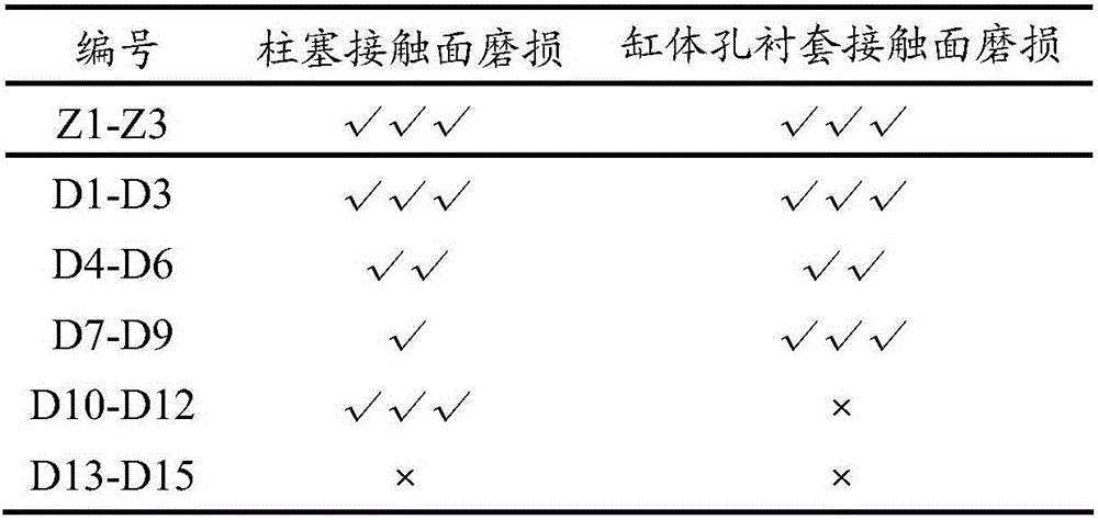
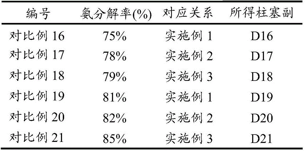
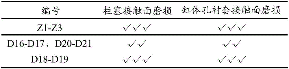
[0045] A method for manufacturing a plunger pair for a plunger pump, wherein the plunger pair includes a plunger and a matching cylinder hole bushing, and the plunger is matched with the cylinder hole bushing The gap is 0.006mm, and the plunger and the cylinder hole bushing are made of specific materials.
[0046] Wherein, the specific material used in the plunger is in weight percent, containing C0.21, Mn0.61, Cr5.0, Ni1.2, Mo0.2, V0.15, Ti0.10, Co0.21, B0 .05, P0.02, S0.02, the balance is Fe and unavoidable impurities;
[0047] The specific material used for the cylinder hole bushing contains C0.25, Mn0.71, Cr4.0, Ni1.4, Mo0.2, V0.19, Ti0.20, Co0.21, P0.01, S0.01, the balance is Fe and unavoidable impurities;
[0048] And, on the contact surface of the two, the plunger is plasma-sprayed with a first ceramic coating with a thickness of 0.5mm, and the first ceramic coating contains 13wt% TiO 2 , the balance being Al 2 o 3 ; The cylinder bore liner is plasma sprayed with a...
Embodiment 2
[0057] A method for manufacturing a plunger pair for a plunger pump, wherein the plunger pair includes a plunger and a matching cylinder hole bushing, and the plunger is matched with the cylinder hole bushing The gap is 0.008mm, and the plunger and the cylinder hole bushing are made of specific materials.
[0058] Wherein, the specific material used in the plunger is in weight percent, containing C0.31, Mn0.71, Cr6.0, Ni1.4, Mo0.3, V0.17, Ti0.20, Co0.31, B0 .07, P0.04, S0.04, the balance is Fe and unavoidable impurities;
[0059] The specific material used for the cylinder hole bushing contains C0.35, Mn0.80, Cr4.5, Ni1.6, Mo0.3, V0.21, Ti0.30, Co0.31, P0.03, S0.02, the balance is Fe and unavoidable impurities;
[0060] And, on the contact surface of the two, the plunger is plasma-sprayed with a first ceramic coating with a thickness of 0.7mm, and the first ceramic coating contains 13wt% TiO 2 , the balance being Al 2 o 3 The cylinder bore liner is plasma sprayed with a t...
Embodiment 3
[0069] A method for manufacturing a plunger pair for a plunger pump, wherein the plunger pair includes a plunger and a matching cylinder hole bushing, and the plunger is matched with the cylinder hole bushing The gap is 0.007mm, and the plunger and the cylinder hole bushing are made of specific materials.
[0070] Wherein, the specific material used in the plunger is in weight percent, containing C0.25, Mn0.65, Cr5.5, Ni1.3, Mo0.25, V0.16, Ti0.15, Co0.25, B0 .06, P0.02, S0.02, the balance is Fe and unavoidable impurities;
[0071] The specific material used in the cylinder hole bushing contains C0.30, Mn0.75, Cr4.2, Ni1.5, Mo0.25, V0.20, Ti0.25, Co0.25, P0.02, S0.02, the balance is Fe and unavoidable impurities;
[0072] And, on the contact surface of the two, the plunger is plasma-sprayed with a first ceramic coating with a thickness of 0.6mm, and the first ceramic coating contains 13wt% TiO 2 , the balance being Al 2 o 3 ; The cylinder bore liner is plasma-sprayed with ...
PUM
| Property | Measurement | Unit |
|---|---|---|
| porosity | aaaaa | aaaaa |
| thickness | aaaaa | aaaaa |
| thickness | aaaaa | aaaaa |
Abstract
Description
Claims
Application Information
 - R&D
- Intellectual Property
- Life Sciences
- Materials
- Tech Scout
- Unparalleled Data Quality
- Higher Quality Content
- 60% Fewer Hallucinations
Browse by: Latest US Patents, China's latest patents, Technical Efficacy Thesaurus, Application Domain, Technology Topic, Popular Technical Reports.
© 2025 PatSnap. All rights reserved.Legal|Privacy policy|Modern Slavery Act Transparency Statement|Sitemap|About US| Contact US: help@patsnap.com