Flue gas recirculation sludge spouted fluidized bed incineration system and method

A spouted fluidized bed and flue gas circulation technology, applied in the combustion method, incinerator, combustion type, etc., can solve the problems affecting the normal operation of the incinerator, blockage of the air distribution plate, and the economic reduction of the incinerator, etc. The effect of temperature, preventing coking in the furnace, and high specific heat capacity

Active Publication Date: 2016-06-29
WUXI GUOLIAN ENVIRONMENTAL SCI & TECH
View PDF5 Cites 5 Cited by
  • Summary
  • Abstract
  • Description
  • Claims
  • Application Information

AI Technical Summary

Problems solved by technology

[0005] For this reason, the technical problem to be solved by the present invention is that in the actual operation process of the fluidized bed incinerator of the prior art, solid phase substances such as fly ash in the circulating flue gas cause the air distribution plate to be blocked, affecting the normal operation of the incinerator. Problems that reduce the economical efficiency of incinerators

Method used


Image

  • Flue gas recirculation sludge spouted fluidized bed incineration system and method
  • Flue gas recirculation sludge spouted fluidized bed incineration system and method

Examples


Embodiment 1

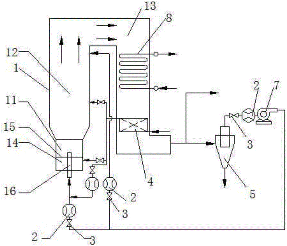
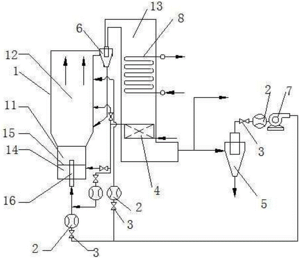
[0031] Such as figure 1 or figure 2 As shown, this embodiment provides a flue gas circulating sludge sprayed fluidized bed incineration method, including: when the fluidized bed incinerator 1 is incinerated, part of the low-temperature flue gas and part of the primary air are blown by the sprayed wind Introduce the incineration dense-phase zone 11 in the form of incineration, so that the incineration dense-phase zone 11 is in a spray fluidized state; the remaining part of the primary air is introduced into the incineration dense-phase zone 15 through the air distribution plate 15; the remaining part of the low-temperature flue gas is introduced into the incineration dilute-phase zone 12 The area near the flue 13; wherein, the total flow ratio of the primary air to the low-temperature flue gas is 0.48-0.96:1.

[0032] The above technical solution is the core technical solution of the flue gas circulating sludge sprayed fluidized bed incineration method of the present inventio...

Embodiment 2

[0038] Such as figure 1 As shown, the present embodiment provides an incineration system using the above-mentioned incineration method, including a fluidized bed incinerator 1, which includes an incineration dense-phase area 11 and an incineration dilute-phase area 12, and the lower part of the incineration dense-phase area 11 is provided with a Plate 15, an air chamber 14 is arranged below the air distribution board 15; the remaining part of the primary air inlet is arranged on the air chamber 14; a nozzle 16 is also included, and the nozzle 16 passes through the air chamber. The chamber 14 and the air distribution plate 15 make the nozzle of the nozzle 16 located in the incineration dense-phase area 11, and the other end communicates with part of the low-temperature flue gas inlet and part of the primary air inlet; The remaining low-temperature flue gas inlet is provided in the area 12 and close to the flue 13 ; the incineration dilute phase area 12 communicates with the flu...


PUM


Abstract

The invention relates to a flue gas recirculation sludge spouted fluidized bed incineration method. The method includes the steps that when an fluidized bed incinerator conducts incineration, part of low temperature flue gas and part of primary air are led into an incineration dense-phase zone in a manner of spouted air, and the incineration dense-phase zone is in the spouted fluidized state; the remaining part of primary air is led into the incineration dense-phase zone through an air distribution plate; in this way, the incineration dense-phase zone is in the spouted fluidized state all the time; and meanwhile, the remaining part of primary air is led into the incineration dense-phase zone through the air distribution plate, the air in the above two manners and the flue gas are led in a mutual matched manner, the problem that in the prior art, an air distribution plate is blocked due to the fact that air is led in through the air distribution plate only is solved. Meanwhile, an incineration system using the above incineration method is disclosed. The total flow ratio of the primary air to the low-temperature flue gas is 0.48-0.96:1; and by means of the above proportion, the incineration effect of the incineration system is better.

Description

technical field [0001] The invention relates to the technical field of waste combustion treatment devices, in particular to a flue gas circulation sludge spray fluidized bed incineration system and method. Background technique [0002] With the development of the economy, more and more sludge is produced in life and industry. In order to effectively solve the secondary pollution of the sludge and affect human health, it is necessary to treat the sludge. Among the numerous sludge treatment and disposal processes, the incineration method can minimize the volume of sludge, kill all germs and pathogens, and completely oxidize and decompose toxic and harmful organic substances. It has become one of the main development directions and research hotspots of sludge treatment and disposal to realize the goals of reduction, harmlessness and resource utilization. Sludge incineration equipment includes multi-chamber incinerators, rotary kiln incinerators and fluidized bed incinerators, ...

Claims


Application Information

Patent Timeline
Patent Type & Authority Applications(China)
IPC IPC(8): F23G7/00F23G5/30F23G5/46
CPCF23G5/30F23G5/46F23G7/001F23G2203/502F23G2206/10F23G2209/12
Inventor 陈晓平江子箫杨叙军宋联朱葛马吉亮刘道银梁财
Owner WUXI GUOLIAN ENVIRONMENTAL SCI & TECH
Why Eureka
Try Eureka