Device and method for bending crossbeam stress corrosion test

A stress corrosion and beam technology, applied in measuring devices, weather resistance/light resistance/corrosion resistance, and application of stable tension/pressure to test the strength of materials, etc. problem, to reduce misleading effect and reduce risk

Inactive Publication Date: 2016-06-29
INST OF METAL RESEARCH - CHINESE ACAD OF SCI
View PDF6 Cites 13 Cited by
  • Summary
  • Abstract
  • Description
  • Claims
  • Application Information

AI Technical Summary

Problems solved by technology

Each of these tests has its own disadvantages
In some tests, such as bending beam test and U-shaped bending test, the bending beam specimen made of high-strength material will break quickly, and the fragments will fly out at high speed, which is extremely dangerous. The personnel who install and test the specimen must take corresponding measures. protection from harm
In addition, in the bending beam test, the stability of different tests is difficult to guarantee, and the deformation generally can only be within the elastic range of the sample material, exceeding the elastic deformation, and the test results are difficult to control
Although the U-shaped bending test is relatively simple, its deformation is large, the test is unstable, and cracks are likely to appear after the sample is formed, which will mislead the subsequent stress corrosion test, and the U-shaped bending test cannot control the difference between different tests. stability, which limits its ability to assess stress corrosion susceptibility
Although the uniaxial loading tensile test can quantitatively study stress corrosion, only one sample can be carried out for each test, which is cumbersome and inefficient

Method used


Image

  • Device and method for bending crossbeam stress corrosion test
  • Device and method for bending crossbeam stress corrosion test
  • Device and method for bending crossbeam stress corrosion test

Examples


Embodiment 1

[0068] The bending beam test with gap in this embodiment includes the following contents:

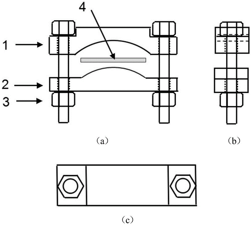
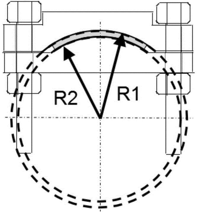
[0069] The design of the fixture in the present invention. The materials used in experimental sample 4 are 316L stainless steel and 308L stainless steel for welding, which belong to the face-centered cubic structure and have good shaping, so the surface strain is selected as 3%. The sample size is selected as 35mm×10mm×2mm. Using the simple estimation method, the arc radii required for the test are calculated as follows: the arc radius of the concave surface of the concave fixture is 34.3mm, and the arc radius of the convex surface of the convex fixture is 32.3mm. The fixture material is 316L stainless steel. In order to ensure that the sample is in a proper position in the fixture, the arc length of the convex surface is selected as 40mm, and the corresponding arc length of the concave surface is calculated as 47.8mm. The width of the fixture is selected as 10mm, and the length is s...

Embodiment 2

[0074] The main difference between Embodiment 2 of the present invention and Embodiment 1 lies in the test fixture, and other contents may refer to Embodiment 1.

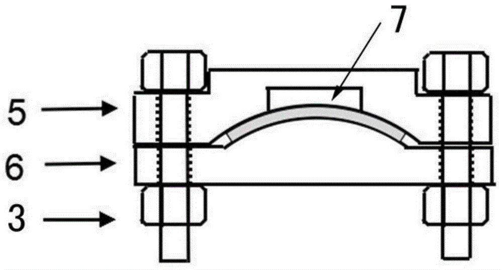
[0075] The schematic diagram of the test fixture structure of the present invention is Figure 5 , consists of two concave clamps II5 with 7 grooves, one male clamp II6 and two loading bolts 3. The male grip II6 in the test fixture consists of two convex faces. Each convex surface corresponds to a concave fixture II5 with a groove 7, and coincides with the center of its arc surface, and its radius is consistent with the size of the sample preparation fixture, namely 34.3mm and 32.3mm. Bolt holes with a diameter of 8.5mm are left on both sides of the concave fixture II5 and the convex fixture II6 of the test fixture respectively. The central axes of the holes coincide and have the same size, and M8 bolts are used. The minimum distance between the bottom of the groove 7 and the surface of the sample in the two groov...

Embodiment 3

[0077] The main difference between Embodiment 3 of the present invention and Embodiment 1 lies in the test fixture, and other contents may refer to Embodiment 1.

[0078] The schematic diagram of the test fixture structure of the present invention is Image 6, consisting of a concave clamp II5 with double grooves 7, a male clamp II6 and two loading bolts 3. The convex fixture II6 in the test fixture can be the same as the convex fixture I2 of the sample preparation fixture in Example 1. The center of the arc surface of the convex fixture II6 coincides with the arc surface of the concave fixture II5 with double grooves 7, and its radius is consistent with the size of the sample preparation fixture, namely 34.3mm and 32.3mm. Bolt holes with a diameter of 8.5mm are left on both sides of the concave fixture II5 and the convex fixture II6 of the test fixture respectively. The central axes of the holes are coincident and the same size, and M8 bolts are used. The minimum distance b...


PUM

PropertyMeasurementUnit
radiusaaaaaaaaaa
radiusaaaaaaaaaa

Abstract

Belonging to the field of corrosion science and protection technologies, the invention discloses a device and method for bending crossbeam stress corrosion test, and mainly studies the stress corrosion behavior of metals (including alloys, also be applicable to other materials). The method includes a loading deformation part and an experimental part. Mainly a groove equipped concave clamp with a predesigned fixed deformation amount and a convex clamp are used in coordination, loading bolts apply force, and retain the force in an experimental environment. A same fixed strain can be applied effectively to different samples to safely, conveniently and efficiently assess the material's stress corrosion susceptibility, including the influence of sample composition, microstructure, stress state or corrosive environment and other factors' changes to stress corrosion susceptibility.

Description

technical field [0001] The invention relates to the technical field of test methods and devices for studying the stress corrosion behavior of metals (including alloys, which can also be used for other materials), in particular to a device and method for stress corrosion tests of curved beams, which are suitable for stress corrosion behavior research in fluid environments . Background technique [0002] Stress corrosion is one of the most common forms of environmental failure in modern industry, often causing major accidents. Stress corrosion cracking is a process from local defect initiation to slow steady state expansion caused by corrosion behavior under the joint acceleration of sensitive material structure, stress and corrosive medium. Its influencing factors are inseparable from three important conditions, namely sensitive material structure and performance, complex stress and corrosion environment. [0003] The currently known evaluation of stress corrosion sensitivi...

Claims


Application Information

Patent Timeline
Patent Type & Authority Applications(China)
IPC IPC(8): G01N3/08G01N3/18G01N17/00
Inventor 彭群家韩姚磊韩恩厚柯伟
Owner INST OF METAL RESEARCH - CHINESE ACAD OF SCI
Why Eureka
Try Eureka