3D AMR groove filling technique

A process method and trench filling technology, applied in the field of 3DAMR trench filling process, can solve the problems affecting etching, uplift, etc., and achieve the effect of improving flatness

Inactive Publication Date: 2016-06-29
SHANGHAI HUAHONG GRACE SEMICON MFG CORP
View PDF2 Cites 2 Cited by
  • Summary
  • Abstract
  • Description
  • Claims
  • Application Information

AI Technical Summary

Problems solved by technology

Due to factors such as the surface tension of the material and its adhesion to the wafer surface during the baking process, the filling material is prone to bulging defects before the trench and further affects the etching, such as figure 2 shown

Method used


Image

  • 3D AMR groove filling technique
  • 3D AMR groove filling technique
  • 3D AMR groove filling technique

Examples


Embodiment Construction

[0022] In order to have a more specific understanding of the technical content, characteristics and effects of the present invention, now in conjunction with the accompanying drawings, the present invention is described in detail as follows:

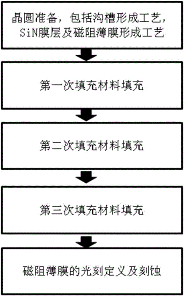
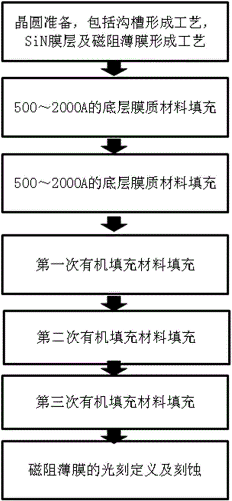
[0023] 3DAMR trench filling process method of the present invention, such as image 3 As shown, it specifically includes the following steps:

[0024] Step 1, wafer preparation: etching to form grooves, and forming SiN film layer and NiFe / TaN magnetoresistive film through SiN deposition process and magnetoresistive film forming process.

[0025] Step 2, fill in the bottom of the trench The underlying membranous material. The underlying film material can be a commonly used BARC (bottom anti-reflection layer) organic material (a type of photoresist).

[0026] The underlying film material is required to have strong adhesion to the wafer surface, and its thickness is usually

[0027] Step 3, on the basis of the underlying membrane mat...


PUM


Abstract

The invention discloses a 3D AMR groove filling technique, which comprises the following steps: (1) forming a groove and a magnetoresistance film on the surface of a wafer; (2) filling the bottom part of the groove with 500-2,000angstrom underlying membranous material; (3) filling the 500-2,000angstrom underlying membranous material again on the basis of the underlying membranous material filled in the step (2); and (4) filling the underlying membranous material filled in the step (3) with an organic filler material in three steps. By the characteristics of the adhesivity between different materials, the fill capability of the material and the like, the flatness of the wafer surface before pattern definition of the magnetoresistance film in a Z direction is improved by a filling method employing twice underlying membranous material filling and triple material filling, so that normal subsequent magnetoresistance film etching is ensured.

Description

technical field [0001] The invention relates to the field of semiconductor integrated circuit manufacturing, in particular to a 3DAMR trench filling process method. Background technique [0002] 3DAMR is based on the Anisotropic Magnetoresistance (AMR) effect, that is, when the applied magnetic field is perpendicular to the current in the ferromagnetic material, the resistance produces a significant change. It is prepared on a silicon wafer or other substrate by using standard semiconductor technology A magnetic sensor with X, Y, Z3D induction formed by the integration of ferromagnetic film strips, supplemented by peripheral circuits and control ICs. [0003] Due to the advantages of low power consumption, high integration, high sensitivity, low noise, high reliability and strong resistance to harsh environments, anisotropic magnetoresistive sensors account for an increasing proportion of magnetoresistive sensors. The field of application is also gradually expanding. [00...

Claims


Application Information

Patent Timeline
IPC IPC(8): H01L43/12
CPCH10N50/01
Inventor 王辉王雷
Owner SHANGHAI HUAHONG GRACE SEMICON MFG CORP
Why Eureka
Try Eureka