
Permanent magnet coupling

A technology of permanent magnetic coupling and permanent magnetic block, which is applied in the direction of permanent magnetic clutch/brake, electric brake/clutch, electrical components, etc., and can solve problems such as sparks, steel plate heating, and permanent magnetic coupling burning , to achieve active use, reduce operating temperature, and improve heat dissipation efficiency

Inactive Publication Date: 2016-06-29
贾建伟
View PDF7 Cites 3 Cited by
  • Summary
  • Abstract
  • Description
  • Claims
  • Application Information

AI Technical Summary

Problems solved by technology

[0007] The purpose of the present invention is to solve the problem that the permanent magnet rotor of the permanent magnet coupling rubs against the copper disc inside the squirrel-cage rotor, causing the steel disc to heat up instantaneously or generate sparks, resulting in the accident of burning the permanent magnet coupling. A permanent magnetic coupling is designed to ensure the safe operation of the high-power motor and the towed conveyor at full load

Method used


Image

  • Permanent magnet coupling
  • Permanent magnet coupling
  • Permanent magnet coupling

Examples


Embodiment Construction

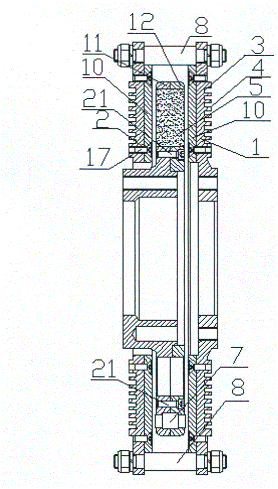
[0024] Referring to the accompanying drawings, figure 1 The main drawing (designated as the accompanying drawing of the abstract of the specification), figure 1 The left side is the load side, which is connected with the reducer, and the right side is the motor side. A plurality of neodymium-iron-boron permanent magnet blocks 5 of the permanent magnet coupling are made into a trapezoidal shape, and are embedded in the trapezoidal groove 18 on the disk. Compared with the existing rectangular permanent magnet block, the trapezoidal permanent magnet block 5 can fully Utilizing the area of ​​the disk improves the utilization rate of the effective area of ​​the disk, and has the effect of obviously increasing the area of ​​the permanent magnet block and increasing the magnetic flux.

[0025] The main disk 11 and the auxiliary disk 12 are fastened and assembled, and are fastened by cylindrical head screws 21 to form a permanent magnet rotor; the main disk 11 is provided with a main...


PUM


Abstract

A permanent magnet coupling belongs to the technical field of motor and drive, is applicable to soft start connection of motor driven pumps, wind driven generators, mine conveyors and other devices, and is to solve the problem that since a permanent magnet rotor has friction with a steel disk at the inner side of a squirrel-cage type rotor, the temperature of a steal disk rises instantly to generate sparks, thus burning up the permanent magnet coupling. The permanent magnet coupling is mainly characterized in that multiple ring-shaped grooves and multiple ring-shaped edges are arranged at at the outer sides of main and auxiliary steel disks which constitute the squirrel-cage type rotor, wherein the ring-shaped grooves and the ring-shaped edges constitute cooling grills; nonmetal warning pins are inlaid among permanent magnet blocks on the permanent magnet rotor composed of main and auxiliary magnet disks, two end heads of each warning pin are respectively slightly raised out of the surface of the permanent magnet rotor and a quantitative clearance is reserved between the two end heads and a copper disk of the squirrel-cage type rotor; when the squirrel-cage type rotor or the permanent magnet rotor has deviation, the warning pins and the copper disk of the squirrel-cage type rotor generate spark-free friction so that a temperature sensor at the outer side of the steel disk transmits ultimate temperature to a controller to carry out power-off protection, thus effectively protecting the operation safety of the permanent magnet coupling and further achieving an active safety effect.

Description

technical field [0001] The invention belongs to the technical field of motors and drives, and specifically relates to a permanent magnet coupling used for connecting a motor (hereinafter referred to as a motor) and a load end. Background technique [0002] Existing permanent magnet couplings are widely used in motors to drive water pumps, fans, mine belt conveyors and other equipment. For example, mine belt conveyors are driven by connecting motors and reducers through permanent magnet couplings. [0003] At present, the known permanent magnetic couplings are generally divided into torque-limiting type, cylindrical type, and standard type according to the manufacturing structure. The basic structure of the standard type permanent magnetic coupling mainly includes the main steel plate with eddy current copper plate, The auxiliary steel plate, the rigid magnetic disk with permanent magnets, and a plurality of permanent magnets are arranged on the magnetic disks. During assemb...

Claims


Application Information

Patent Timeline
Patent Type & Authority Applications(China)
IPC IPC(8): H02K49/10
CPCH02K49/104
Inventor 贾建伟李慧生
Owner 贾建伟
Learn More