High-energy rotary magnetic massage armchair structure

A massage chair, high-energy technology, applied in the use of variable magnetic fields generated by mechanical movement, passive exercise equipment, physical therapy, etc., can solve problems such as insufficient optimization of magnetic field distribution, unfavorable mute, heat dissipation, and poor physical properties. Achieve the effect of high effective utilization of magnetic field, better magnetic health care effect, and scientific and reasonable structure

Active Publication Date: 2016-07-06
HEYE HEALTH TECH CO LTD
View PDF12 Cites 3 Cited by
  • Summary
  • Abstract
  • Description
  • Claims
  • Application Information

AI Technical Summary

Problems solved by technology

[0002] Many existing massage chairs have begun to use the related equipment of rotating magnetic field. However, the technology of the rotating magnetic equipment used in the existing massage chairs is not mature enough. The structure of the gyromagnetic equipment obtained is not stable enough, and it has problems such as large motor power, high energy consumption, large space occupation, large vibration, high noise, poor heat dissipation, poor physical performance, insufficient optimization of magnetic field distribution, and low effective utilization rate. It is conducive to the setting of a strong magnetic field, the production cost is also high, and the magnetic health care effect is not good, and the existing internal structure design is not reasonable enough, especially the massage chair that needs to be equipped with a rotating magnetic device, such as a lifting mechanism or a push rod mechanism High-end chairs are often not well integrated with gyromagnetic equipment, poor compatibility, unfavorable assembly, easy to damage, and cannot achieve a good magnetic health care space environment, and are also not conducive to quietness, heat dissipation, etc.

Method used


Image

  • High-energy rotary magnetic massage armchair structure
  • High-energy rotary magnetic massage armchair structure
  • High-energy rotary magnetic massage armchair structure

Examples


Embodiment 1

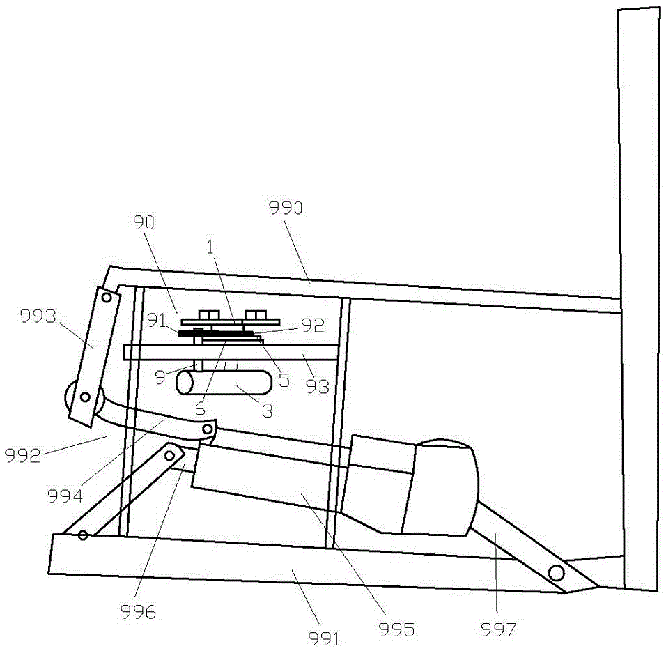
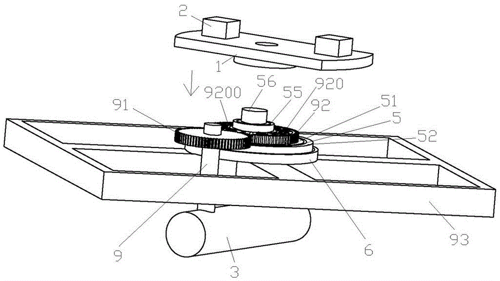
[0031] Example 1, such as figure 1 , 2 As shown in , 3, a high-energy gyromagnetic massage chair structure, a high-energy gyromagnetic device 90 is provided below the seat 990 of the massage chair, and a liftable A telescopic footrest mechanism 992 for resting the feet, the telescopic footrest mechanism 992 includes a leaning rod 993 hinged to the seat 990 on the front side of the high-energy gyrator 90, and a hinged hinged rod 993 located near the high-energy gyratory to the other end of the leaning rod 993. The curved rod 994 at the front and bottom of the magnetic device 90, and the telescopic cylinder 995 located below the high-energy gyrator 90 that are hinged to the other end of the curved rod 994, the piston rod 996 of the telescopic cylinder 995 is hinged with a lower support rod 997, and the lower rod 997 is hinged. The other end of pole 997 is hinged with the position near the front end of chair bottom 991, and the rear end of telescopic cylinder 995 is hinged w...

Embodiment 2

[0036] Example 2, such as Figure 4 , 5 As shown, the difference between it and Embodiment 1 is: the design of the magnetic assembly 2. In this embodiment, the first solution, the magnetic assembly 2 includes the base main pole piece 71 installed on the base rotating disk 1, the base main pole piece 71 can be used alone as the magnetic assembly 2 directly, and a cuboid or cube-shaped magnetic pole piece with a relatively large surface magnetic field strength can be used; in the second scheme, the magnetic assembly 2 not only includes the base main magnetic pole piece 71, but also includes the upper main magnetic pole piece 72, The upper main magnetic pole piece 72 is arranged on the top of the base main magnetic pole piece 71, and the upper main magnetic pole piece 72 can also adopt a cuboid or cube-shaped magnetic pole piece with a larger surface magnetic field strength. The upper main magnetic pole piece 72 and the base main magnetic pole piece 71 The size can be set to ...

Embodiment 3

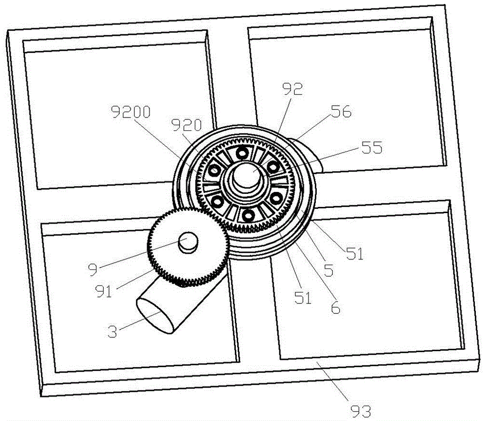
[0037] Example 3, such as Image 6 As shown, the difference between it and Embodiment 1 or 2 is that: the outer side of the magnetic assembly 2 is covered with a protective cover 8, and the lower part of the protective cover 8 extends to form a cover installation piece 80 for fixed connection with the basic rotating disk 1. The cover installation piece 80 can be installed and fixed with the basic rotating disk 1 through screws, etc. The protective cover 8 is a non-magnetic isolation stainless steel cover, that is, a non-magnetic stainless steel outer cover can be used, which is not only beautiful, but also protects the magnetic pole pieces from oxidation and prevents ferromagnetic objects from being directly Collision and contact with the magnetic pole piece can also prevent the magnetic assembly 2 from falling off during high-speed operation and cause accidents, further optimize the structure and force distribution, improve various physical properties, and have a better magn...


PUM


Abstract

The invention relates to the technical field of rotary magnetic field devices, in particular to a high-energy rotary magnetic massage armchair structure. A high-energy rotary magnetic device is arranged below a chair seat of a massage armchair. A liftable stretchable foot resting mechanism for foot resting is arranged between the chair seat and the chair bottom of the massage armchair. The stretchable foot resting mechanism comprises a leaning rod, a bent rod and a stretchable air cylinder, wherein the leaning rod is close to the front side of the high-energy rotary magnetic device and hinged to the chair seat, the bent rod is hinged to the other end of the leaning rod and close to the portion below the front portion of the high-energy rotary magnetic device, and the stretchable air cylinder is hinged to the other end of the bent rod and located below the high-energy rotary magnetic device. A lower supporting rod is hinged to a piston rod of the stretchable air cylinder. The other end of the lower supporting rod is hinged to the portion, close to the front end, of the chair bottom. The rear end of the stretchable air cylinder is hinged to the portion, close to the rear end, of the chair bottom. The high-energy rotary magnetic massage armchair structure is more scientific and reasonable in structure, high in compatibility and good in magnetic health care effect.

Description

technical field [0001] The invention relates to the technical field of rotating magnetic field equipment, in particular to a high-energy rotating magnetic massage chair structure. Background technique [0002] Many existing massage chairs have begun to use the related equipment of rotating magnetic field. However, the technology of the gyromagnetic equipment used in the existing massage chairs is not mature enough, and the structure of the gyromagnetic equipment used is not stable enough. High power consumption, large space occupation, large vibration, high noise, poor heat dissipation, etc., poor physical performance, insufficient optimization of magnetic field distribution, low effective utilization rate, usually not conducive to the setting of strong magnetic fields, high production costs, and low magnetic health care effects Not good, and the existing internal structure design is not reasonable enough, especially massage chairs that need to be equipped with gyromagnetic ...

Claims


Application Information

Patent Timeline
Patent Type & Authority Applications(China)
IPC IPC(8): A61H1/00A61N2/12
CPCA61H1/00A61H2201/0149A61H2201/10A61N2/12
Inventor 方志财胡立江王柏林汪富兵李俊
Owner HEYE HEALTH TECH CO LTD
Why Eureka
Try Eureka