
An automatic cleaning device for auto parts

A technology for automatic cleaning and auto parts, applied in the direction of cleaning methods using liquids, cleaning methods and utensils, chemical instruments and methods, etc., can solve the problems of poor control of cleaning standards, inability to meet industrial production, and high labor intensity, etc., to achieve The effect of simple structure, saving space and reducing labor intensity

Active Publication Date: 2018-02-13
JIANGSU BOYINGTE ELECTRONICS TECH CO LTD
View PDF7 Cites 0 Cited by
  • Summary
  • Abstract
  • Description
  • Claims
  • Application Information

AI Technical Summary

Problems solved by technology

[0002] In the production process of auto parts, it is usually necessary to turn and drill the products. Therefore, a large amount of cutting fluid, metal chips and other sundries are usually attached to the parts of the car. Before the car is assembled, it must be To clean each spare part, the traditional cleaning method is to put the parts into the cleaning solution and clean them manually. This method is very inefficient and labor-intensive, and cannot meet modern industrial production. The standard is not easy to control, and due to human factors, it is easy to cause damage to some more sophisticated devices, because it is necessary to invent a device that can be cleaned automatically

Method used


Image

  • An automatic cleaning device for auto parts
  • An automatic cleaning device for auto parts
  • An automatic cleaning device for auto parts

Examples


Embodiment Construction

[0021] In order to make the object, technical solution and advantages of the present invention more clear, the present invention will be further described in detail below in conjunction with the examples. It should be understood that the specific embodiments described here are only used to explain the present invention, not to limit the present invention.

[0022] The application principle of the present invention will be described in detail below in conjunction with the accompanying drawings.

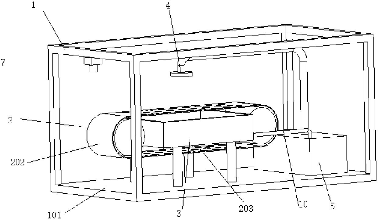
[0023] An automatic cleaning device for auto parts, comprising a bracket 1, a feeder 2, a drainage device 3, a spray device 4, a cleaning liquid container 5, a water pump 6, a camera 7, and a controller 8; There is a bottom plate 101; the feeder 2 is installed on the support 1, which includes two conveying rollers 202 driven by a motor 201 and a conveying belt 203 with several water leakage holes; the drainage device 3 is installed on the support 1 , located between the upper and lowe...


PUM


Abstract

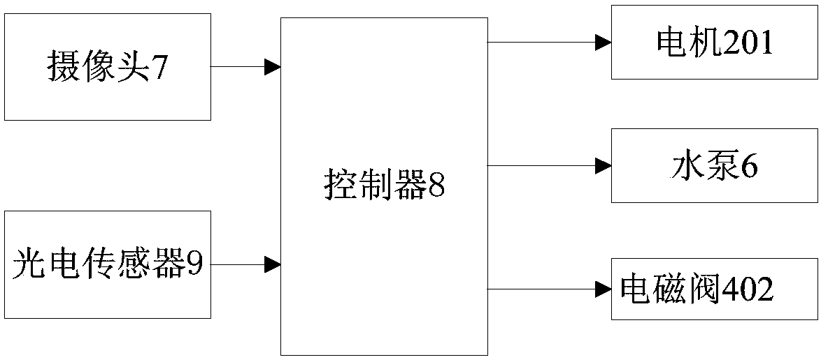
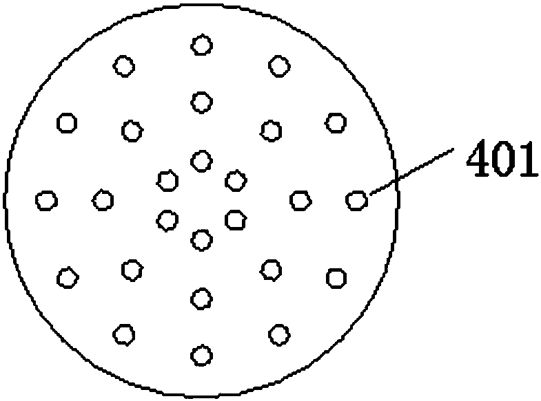
The invention discloses an automatic cleaning device for automobile parts. The automatic cleaning device comprises a support frame, a material conveying machine, a water discharging device, a spraying device, a cleaning liquid container, a water pump, a camera and a controller, wherein the bottom of the support frame is provided with a bottom plate; the material conveying machine is arranged on the support frame and comprises two material conveying rollers and a material conveying belt; the material conveying rollers are driven by a motor; the material conveying belt is provided with holes; the water discharge device is positioned between the upper surface and the lower surface of the material conveying machine; the top of the water discharge device is provided with an opening; the bottom of the water discharge device is provided with a liquid outlet; the spraying device is positioned above the material conveying machine, and comprises a plurality of sealed spraying head groups in concentric arrangement; an inlet of each spraying head group is connected with the water pump through an electromagnetic valve; the water pump is positioned in the cleaning liquid container; the camera is positioned above the input end of the material conveying machine; the data transmission end of the camera is connected with the controller; the controller is connected with each electromagnetic valve, the motor and the control end of the water pump respectively. The automatic cleaning device has the advantages that different cleaning modes can be automatically selected by aiming at parts in different dimensions; the cleaning liquid can be effectively saved; the cleaning cost is reduced.

Description

technical field [0001] The invention belongs to the technical field of automobile equipment, and in particular relates to an automatic cleaning device for automobile parts. Background technique [0002] In the production process of auto parts, it is usually necessary to turn and drill the products. Therefore, a large amount of cutting fluid, metal chips and other sundries are usually attached to the parts of the car. Before the car is assembled, it must be To clean each spare part, the traditional cleaning method is to put the parts into the cleaning solution and clean them manually. This method is very inefficient and labor-intensive, and cannot meet modern industrial production. The standards are not easy to control, and due to human factors, it is easy to cause damage to some relatively sophisticated devices, because it is necessary to invent a device that can be cleaned automatically. Contents of the invention [0003] In view of the above problems, the present invent...

Claims


Application Information

Patent Timeline
Patent Type & Authority Patents(China)
IPC IPC(8): B08B3/02B08B13/00
CPCB08B3/022B08B13/00
Inventor 孟雷军胡国旗
Owner JIANGSU BOYINGTE ELECTRONICS TECH CO LTD
Learn More