
Grease lubricating complete equipment for construction elevator

A complete set of equipment and construction elevator technology, applied in the direction of mechanical equipment, lubricating parts, engine lubrication, etc., can solve the problems of dangerous high-altitude operations, time-consuming and oil-consuming, poor effect, etc., to achieve wide application, low manufacturing cost, Simple structure and practical effect

Active Publication Date: 2016-07-06
张巍
View PDF10 Cites 5 Cited by
  • Summary
  • Abstract
  • Description
  • Claims
  • Application Information

AI Technical Summary

Problems solved by technology

[0002] Construction elevators are the main equipment for vertically transporting building materials in building construction. They must be used in high-rise building construction. During use, the guide rail rollers and gear racks must be lubricated with grease. At present, the construction elevator products produced by domestic manufacturers use artificial The lubrication method of regularly applying butter, although some manufacturers of construction elevator accessories also have a separate butter machine product supply market, is rarely adopted by users due to poor effect or high cost, so the construction industry is still generally behind the construction elevator The manual lubrication method of regular buttering is dirty and tiring, time-consuming and oil-consuming, and dangerous high-altitude operations are also required

Method used


Image

  • Grease lubricating complete equipment for construction elevator
  • Grease lubricating complete equipment for construction elevator
  • Grease lubricating complete equipment for construction elevator

Examples


Embodiment Construction

[0030] Embodiments of the present invention are described in detail below, examples of which are shown in the drawings, wherein the same or similar reference numerals represent the same or similar elements or elements having the same or similar functions throughout.

[0031] In the description of the present invention, it should be noted that for orientation words, such as the term "center", "horizontal", "longitudinal", "length", "width", "thickness", "upper", "lower" , "Front", "Back", "Left", "Right", "Vertical", "Horizontal", "Top", "Bottom", "Inner", "Outer", "Clockwise", "Counterclockwise " and other indication orientations and positional relationships are based on the orientations or positional relationships shown in the drawings, and are only for the convenience of describing the present invention and simplifying the description, rather than indicating or implying that the device or element referred to must have a specific orientation, or in a specific orientation. The...


PUM


Abstract

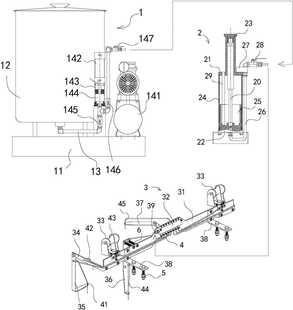
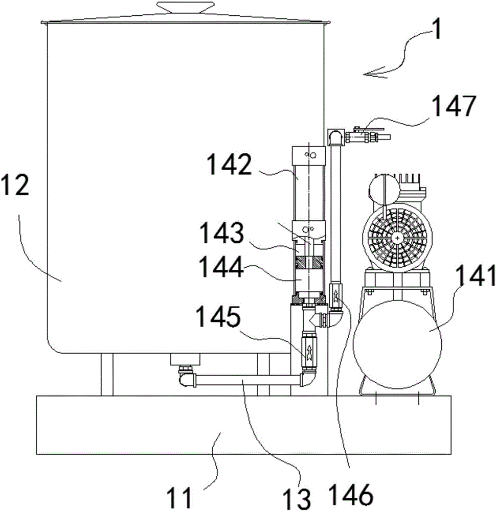
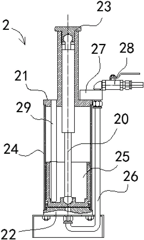
The invention discloses grease lubricating complete equipment for a construction elevator. The grease lubricating complete equipment comprises a main machine system, an energy storage and oil storage system and a grease separating system, wherein the energy storage and oil storage system comprises a front cover, a rear cover, a pressure cover, a cylinder sleeve, a rod-less piston and an oil pipe; a valve seat and a ball valve are arranged on the front cover; an oil maker post and the rod-less piston are arranged in the cylinder sleeve; a gas spring is arranged on the axle center position of the cylinder sleeve, and elastically abuts against between the rod-less piston and the front cover; when grease is injected into a grease cavity, the rod-less piston drives the air spring to be compressed to form an energy storage state; in use, the ball valve is opened for automatically extruding grease; the grease separating system comprises a vertical plate, an adjustable separating block, a grease coating wheel, a side roller bent foot, a positive pressure wheel bent foot, a climbing gear bent foot, a rack back wheel bent foot and a mounting foot, wherein the adjustable separating block is arranged on the vertical plate; and the adjustable separating block is provided with an oil inlet connector and a plurality of oil outlet tubes. The grease lubricating complete equipment is convenient and quick to operate, and integrates use of a main machine for providing dynamic energy source, use of energy storage, separating and conveying.

Description

【Technical field】 [0001] The invention relates to a complete set of butter lubrication equipment for construction elevators. 【Background technique】 [0002] Construction elevators are the main equipment for vertically transporting building materials in building construction. They must be used in high-rise building construction. During use, the guide rail rollers and gear racks must be lubricated with grease. At present, the construction elevator products produced by domestic manufacturers use artificial The lubrication method of regularly applying butter, although some manufacturers of construction elevator accessories also have a separate butter machine product supply market, is rarely adopted by users due to poor effect or high cost, so the construction industry is still generally behind the construction elevator The manual lubrication method of regular buttering is dirty and tiring, time-consuming and oil-consuming, and dangerous high-altitude operations are also required...

Claims


Application Information

Patent Timeline
IPC IPC(8): B66B7/12F16N7/38F16N21/00F16N23/00F16N25/00
CPCB66B7/1253F16N7/38F16N21/00F16N23/00F16N25/00
Inventor 张巍
Owner 张巍
Learn More