Vacuum evaporation apparatus

An evaporation and vacuum technology, which is applied in the directions of vacuum evaporation plating, sputtering plating, ion implantation plating, etc., can solve the problems of decreasing the effect of increasing the incident angle, reducing the proportion of the flat part of the film pattern, and blurring the pattern. , to achieve the effect of suppressing pattern blur and uniform film thickness distribution

Active Publication Date: 2016-07-06
CANON TOKKI CORP
View PDF6 Cites 16 Cited by
  • Summary
  • Abstract
  • Description
  • Claims
  • Application Information

AI Technical Summary

Problems solved by technology

[0011] here, in Figure 4 , 6 in, such as Figure 5 As shown in (b) and (b) of 7, the film thickness distribution can be made uniform by widening the nozzle range and adjusting the inclination angle or arrangement of the spray nozzle 22, but in this case, because the nozzle range is expanded Therefore, the effect of increasing the incident angle decreases, the ratio of the flat portion of the film formation pattern becomes smaller, and it is difficult to suppress pattern blur

Method used


Image

  • Vacuum evaporation apparatus
  • Vacuum evaporation apparatus
  • Vacuum evaporation apparatus

Examples


Embodiment

[0064] Specific embodiments of the present invention will be described with reference to the drawings.

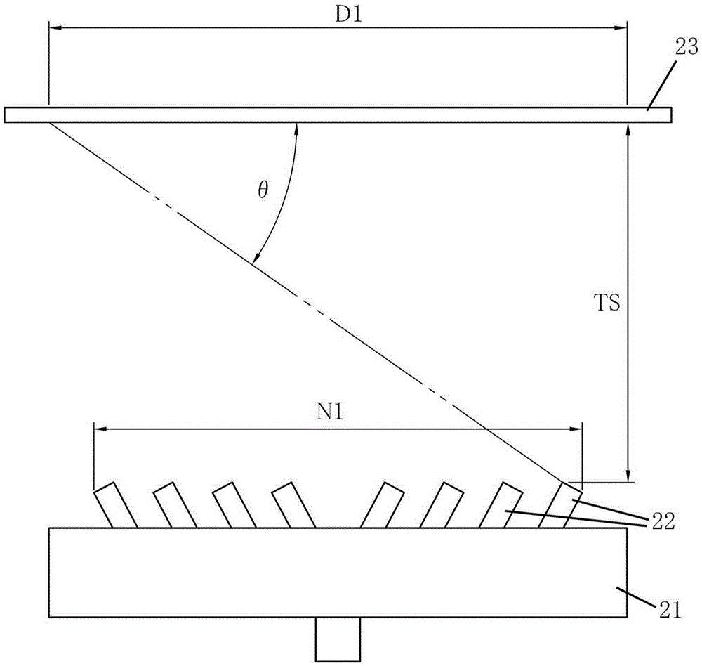
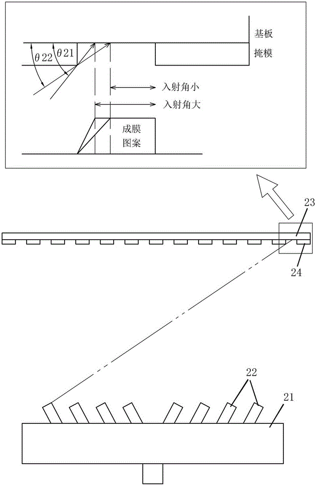
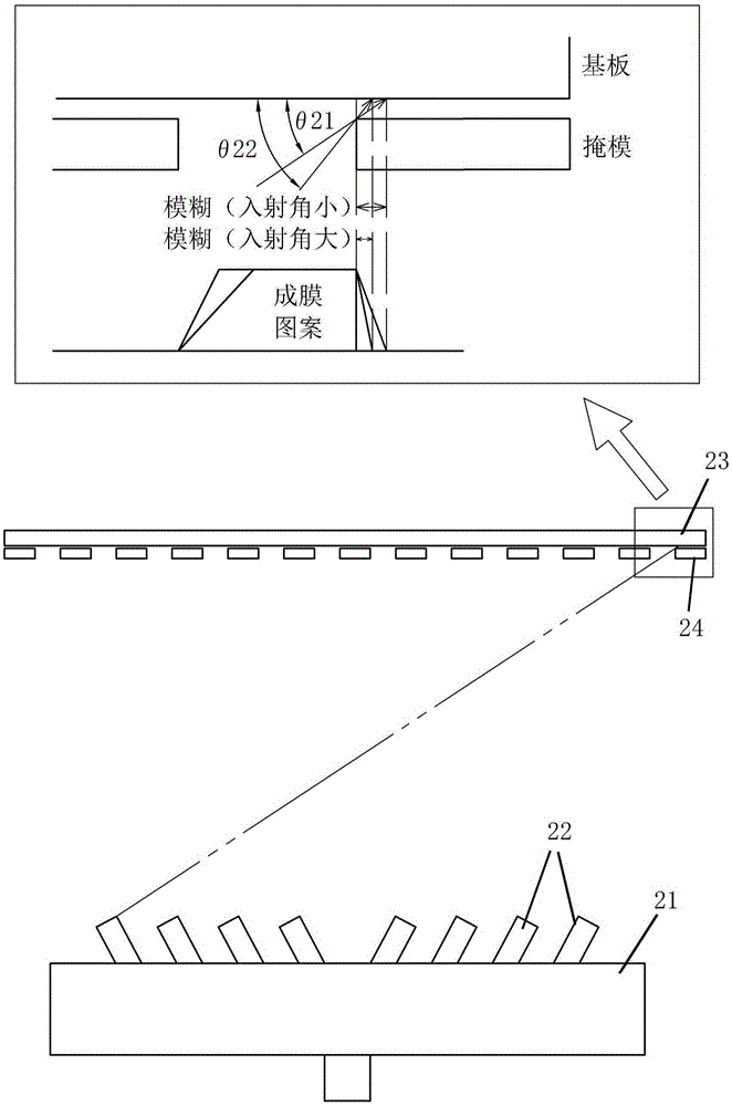
[0065] In this embodiment, the present invention is applied to a vacuum evaporation device configured as follows: an evaporation source 1 containing a film-forming material is arranged in a vacuum tank maintaining a reduced pressure atmosphere, and multiple An evaporation port 2 is used to relatively move the evaporation source 1 and the substrate 3 disposed at a position facing the evaporation source 1 in a direction perpendicular to the longitudinal direction of the evaporation source 1. The film-forming material is ejected from the evaporation port 2 to form a vapor-deposited film on the substrate 3 .

[0066] Specifically, in this embodiment, the outermost evaporation ports 2 provided at the outermost ends of the plurality of evaporation ports 2 are each configured to have an inclination toward the outside in the longitudinal direction of the evaporation source 1 . At ...


PUM


Abstract

The present invention provides a vacuum evaporation apparatus. The blurring phenomenon of a pattern is avoided when the ratio of the flat portion of the film pattern is increased. Meanwhile, an evaporation film with the thickness thereof to be uniformly distributed is obtained. A plurality of evaporation openings (2) are formed on an evaporation source (1) along the length direction of the evaporation source. The evaporation source (1) is capable of moving relative to a substrate (3) arranged opposite to the evaporation source (1) in a direction vertical to the length direction of the evaporation source (1). The film formation material is ejected out of the evaporation openings (2). Therefore, an evaporation film is formed on the substrate (3). At least one pair of external evaporation openings (2), out of the plurality of evaporation openings (2), are respectively provided with an opening end surface inclined towards the outside along the length direction of the evaporation source (1). At least one internal evaporation opening (2), positioned on the inner side of the external evaporation openings (2) and selected out of the plurality of evaporation openings (2), is provided with an opening end surface inclined towards the centre along the length direction of the evaporation source (1).

Description

technical field [0001] The present invention relates to a vacuum evaporation device. Background technique [0002] In a vacuum evaporation device that forms a deposited film on a substrate disposed at a position facing an evaporation source containing a film-forming material, when the angle at which the film-forming material reaches the substrate (incident angle to the substrate) is small In some cases, the proportion of the flat part of the film formation pattern becomes small, or the film formation material penetrates into the gap between the deposition mask and the substrate to cause so-called pattern blurring. In order to form a desired film formation pattern, it is necessary to make the mask The size of the opening becomes unnecessary, and high definition of the film formation pattern cannot be achieved. [0003] Therefore, for example, as disclosed in Patent Document 1, it is proposed to make the range of arrangement of spray nozzles (nozzle range) A technology that ...

Claims


Application Information

Patent Timeline
Patent Type & Authority Applications(China)
IPC IPC(8): C23C14/24
CPCC23C14/225C23C14/24
Inventor 近藤喜成田村博之
Owner CANON TOKKI CORP
Why Eureka
Try Eureka