
Shock Resistant Clutch

A clutch and anti-shock technology, which is applied in clutches, friction clutches, mechanically driven clutches, etc., can solve problems such as high noise in clutch operation, influence on transmission accuracy, large vibration and impact, etc., so as to alleviate impact wear, ensure transmission stability, and guarantee The effect of service life

Active Publication Date: 2020-02-07
广东隆鑫机车有限公司
View PDF11 Cites 0 Cited by
  • Summary
  • Abstract
  • Description
  • Claims
  • Application Information

AI Technical Summary

Problems solved by technology

In the prior art, the clutch realizes power transmission through the power input, and through the engagement and separation between the friction plates. The general structure is to input the power into the active part (such as the outer cover) of the clutch through the power input part (such as a gear or a sprocket) ; In the prior art, the gap between the power input part is installed on the active part, and there is a large axial gap between the power input part and the active part. When the power is input, the impact force is relatively large, forming a large vibration and impact, reducing the power input part. The service life of itself affects the transmission accuracy, and there is a lot of noise; and due to the fit and connection relationship between the power input part and the active part, there is a large impact wear between the two; especially during the start-up process, Not only will it affect the service life, but the above problems will also cause the entire clutch to run noisy, which will also have an adverse effect on the stability of the transmission.

Method used


Image

  • Shock Resistant Clutch

Examples


Embodiment Construction

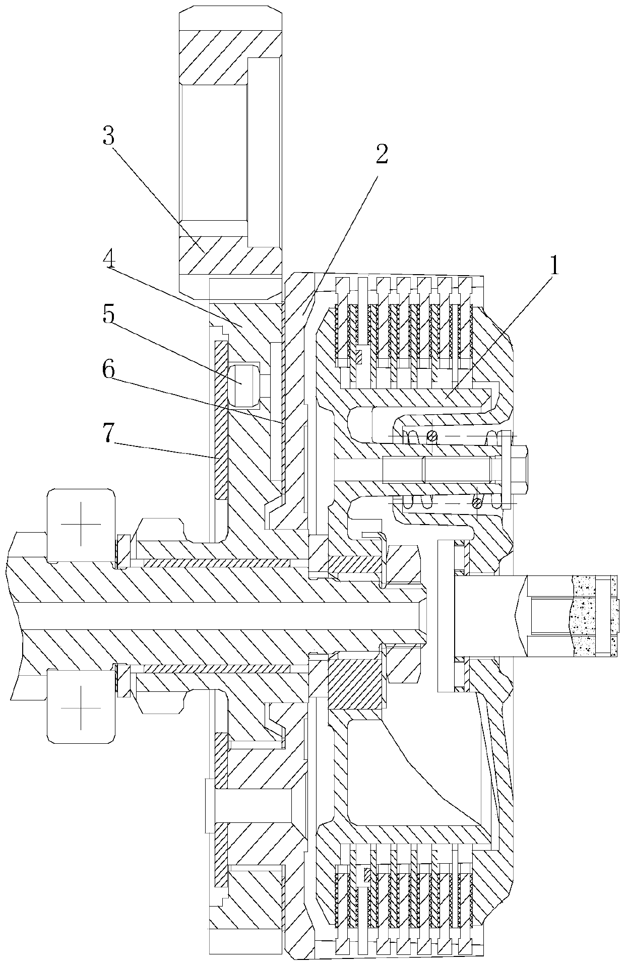
[0018] figure 1 It is a schematic diagram of the structure of the present invention. As shown in the figure, an anti-impact clutch provided by the present invention includes a driving member 2, a driven member 1 and a power input member 4, and also includes a pressing member 7, the pressing member 7 The power input part 4 is press-fitted and installed on the driving part 2 through the shock absorber 5; the driving part 2 generally refers to the clutch cover, of course, it can be different according to the needs of the structure; the driven part 1 is the part that outputs the power through The transmission of the driving friction plate and the driven friction plate belongs to the prior art and will not be repeated here; as shown in the figure, the power input member 4 is generally a power input driven gear, and the power input driving gear 3 is matched with it; The engaging part 7 is connected to the driving part from the axial direction, and presses the power input part between...


PUM


Abstract

The invention provides an anti-impact clutch. The anti-impact clutch comprises a driving part, a driven part and a power input part, and further comprises a press fitting part, wherein the press fitting part is used for mounting the power input part into the driving part through a vibration absorption part in a press fitting manner. By adopting a structure of mounting the power input part into the driving part by utilizing the press fitting part through the vibration absorption part in the press fitting manner, generated vibration and impact can be buffered in starting and transmission processes, and impact abrasion caused by the input of the power input part is alleviated, so that the service life is guaranteed, operation noises are reduced and the transmission stability is guaranteed; meanwhile, the press fitting part also generates a centrifugal force for throwing out lubricating oil along the radial direction, lubrication is formed at the engaged part of the power input part (a power input gear), and the transmission lubrication is guaranteed, so that the service life is prolonged, the transmission stability is further guaranteed and the transmission noises are further eliminated.

Description

Technical field [0001] The invention relates to a transmission equipment component, in particular to an anti-shock clutch. Background technique [0002] For the power transmission system, the clutch is a simple and convenient universal device for cutting off and engaging power; its function is well known in the art and will not be repeated here. In the prior art, the clutch realizes power transmission through power input and through the engagement and separation between the friction plates. The general structure is to input power into the active part (such as the outer cover) of the clutch through the power input component (such as gear or sprocket). In the prior art, the power input part is installed in the active part in the gap, and there is a large axial gap between the power input part and the active part. When the power is input, the impact force is relatively large, resulting in greater vibration and impact, reducing the power input part The service life of itself will af...

Claims


Application Information

Patent Timeline
Patent Type & Authority Patents(China)
IPC IPC(8): F16D13/70F16D13/74F16H57/028F16H57/04
CPCF16D13/70F16D13/74F16H57/028F16H57/042
Inventor 周良兵邹正伟文星闵渝维杜龙
Owner 广东隆鑫机车有限公司
Learn More