Long trace profile

A long-distance surface shape and measuring instrument technology, which is applied to measuring devices, instruments, and optical devices, can solve problems such as errors, and achieve the effects of reducing system errors, reducing the number of optical components, and reducing the amount of lateral movement

Active Publication Date: 2016-07-06
SHANGHAI INST OF APPLIED PHYSICS - CHINESE ACAD OF SCI
View PDF6 Cites 8 Cited by
  • Summary
  • Abstract
  • Description
  • Claims
  • Application Information

AI Technical Summary

Problems solved by technology

from figure 1 It can be seen that the measuring beam starts to deviate from the measuring point on the mirror to be tested 6', so the measuring point on the mirror to be tested 6' is the reference point for calculating the lateral displacement of each optical element in the pp-LTP, so for the same The deflection angle of

Method used


Image

  • Long trace profile
  • Long trace profile
  • Long trace profile

Examples


Embodiment Construction

[0022] Below in conjunction with the drawings, preferred embodiments of the present invention are given and described in detail.

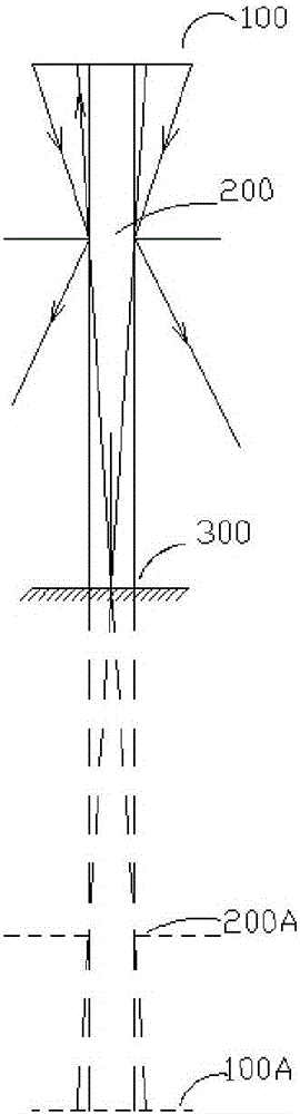
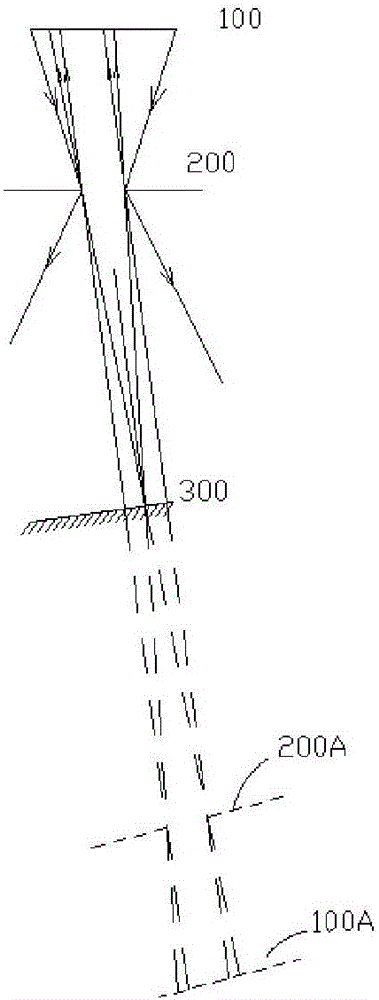
[0023] well known, such as Figure 2a As shown, if the surface light source 100 is horizontally placed behind the hole 200, the light beam emitted by the surface light source 100 passes through the hole 200 and is reflected by the plane mirror 300, which can be regarded as being emitted by the image 100A formed by the plane mirror 300 on the light source 100. Beam through aperture image 200A. It can be seen from the principle of mirror reflection that the light beam passing through the center of the hole 200 and the hole image 200A after mirror reflection must propagate along the normal direction of the plane mirror 300, so the light beam passing through the hole 200 after mirror reflection is a beam that propagates along the normal direction of the mirror surface and has a small The divergence angle of the thin light beam is determined by the dia...


PUM


Abstract

A long trace profile provided by the present invention is used to carry out the profile detection on the surface of a to-be-tested optical device, and comprises a scanning optical head and a f-theta angle detection system. The scanning optical head comprises a surface light source, a beam splitter, a single-hole screen and a plane mirror. The surface light source is placed horizontally, the beam splitter is arranged below the surface light source aslant, the single-hole screen is attached to the bottom surface of the beam splitter tightly, and the plane mirror is arranged below the single-hole screen aslant and forms a dual-reflection surface of a similar pentaprism structure with the beam splitter. According to the present invention, a system error introduced by the lateral movement of a measurement light beam when different angles are measured is reduced, thereby improving the measurement precision.

Description

technical field [0001] The invention relates to the field of high-precision mirror surface shape detection, in particular to a long-distance surface shape measuring instrument. Background technique [0002] In the fields of science and technology such as large-scale astronomical telescopes, extreme ultraviolet lithography, and synchrotron radiation optical engineering, it is necessary to use slender, high-precision mirrors with a length of about 1m and a surface error of less than 0.1 microradians. The production and use of such high-precision optical devices depends on high-precision surface detection technology. [0003] The Long Trace Profile (LTP) based on the principle of point-by-point scanning of thin beams is one of the main instruments used in the detection of such high-precision optical devices. Point-by-point scanning is carried out on the optical device. Since the normal direction of different points on the optical device is different, the reflected light is ref...

Claims


Application Information

Patent Timeline
IPC IPC(8): G01B11/24
CPCG01B11/24
Inventor 彭川黔何玉梅王劼
Owner SHANGHAI INST OF APPLIED PHYSICS - CHINESE ACAD OF SCI
Why Eureka
Try Eureka