Flight body angular velocity measurement method based on vortex light rotation Doppler effect

A technology of Doppler effect and vortex light, which is applied in the field of measuring the angular velocity of flying objects, can solve the problems of multiple sources of noise, large gaps, and short occurrence

Active Publication Date: 2016-07-06
PLA PEOPLES LIBERATION ARMY OF CHINA STRATEGIC SUPPORT FORCE AEROSPACE ENG UNIV
View PDF7 Cites 22 Cited by
  • Summary
  • Abstract
  • Description
  • Claims
  • Application Information

AI Technical Summary

Problems solved by technology

The method of laser gyro has high precision, but the processing is complicated and there are problems of zero point drift and lock-up, and there are many sources of noise; although the processing of fiber optic gyro is simple and high precision, but the system stability is poor, the volume is large, the cost is high, and the impact resistance performance Poor, there is a zero point drift problem, and the accuracy is greatly limited due to the contradiction between accuracy and volume
In terms of technical level, my country's optical gyroscope technology started relatively late. Although it has made many gratifying achievements, its overall level still lags behind that of Western countries, and due to the level of technology, the gap in practical application is even greater.
[0003] At present, the method of measuring the angular velocity of rotating objects by using the rotating Doppler effect of vortex light has appeared in the world not long ago, and it is limited to the system on the ground. There is no relevant institution or individual to apply this method to the measurement of the angular velocity of flying objects.

Method used


Image

  • Flight body angular velocity measurement method based on vortex light rotation Doppler effect
  • Flight body angular velocity measurement method based on vortex light rotation Doppler effect
  • Flight body angular velocity measurement method based on vortex light rotation Doppler effect

Examples


Embodiment Construction

[0044] specific implementation plan

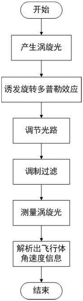
[0045] The implementation object of the present invention is a flying body with angular velocity and attitude changes, and the schematic diagram of the specific embodiment is as follows figure 1 As shown, the specific implementation steps are as follows:

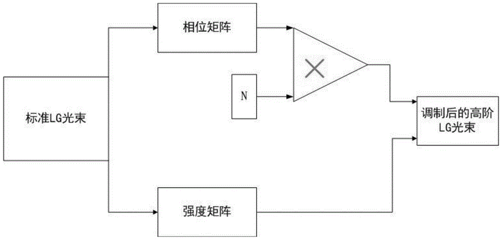
[0046] (1) Generate vortex light with high-order angular momentum

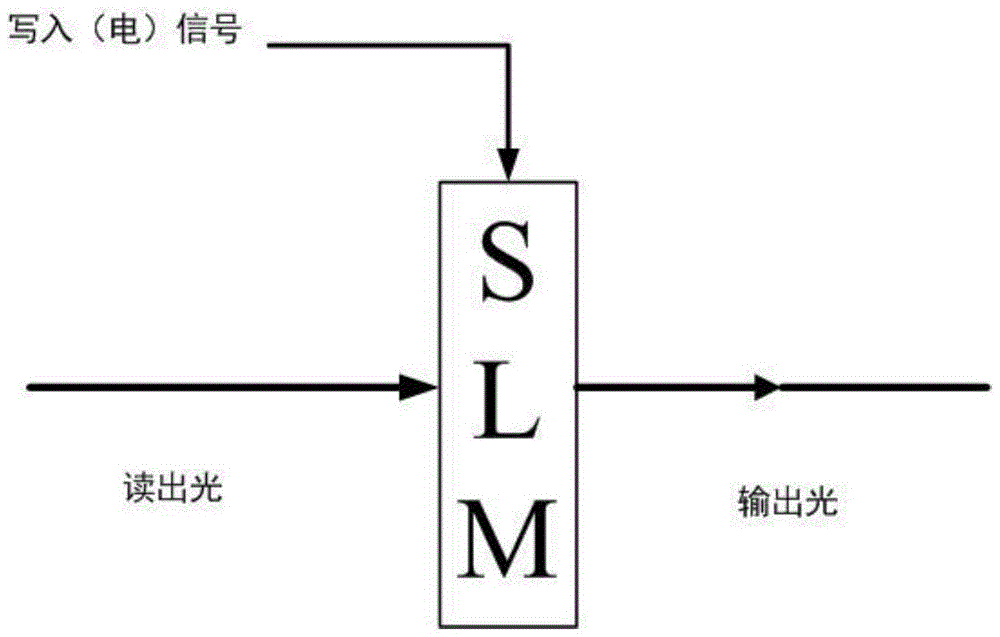
[0047] Place the HG beam laser with better monochromaticity and the SLM coaxially on the rotation axis of the dimension of the flying object to be measured, as shown in figure 1 As shown, the wave function expression of Laguerre-Gaussian beam (referred to as LG beam) is:

[0048] LG p l ∝ 1 1 + Z 2 ...


PUM


Abstract

The present invention relates to a flight body angular velocity measurement method based on a vortex light rotation Doppler effect. The flight body angular velocity measurement method based on vortex light rotation Doppler effect is characterized in that according to the vortex light rotation Doppler effect principle, a vortex light generation system and a measurement system are placed on a flight body rotating shaft; firstly, the vortex light of which the orbital angular momentum topological charge number is 1 is generated according to a vortex light wave function and by utilizing a phase modulation method; the vortex light generation system and the synchronous rotation of a vortex light beam and a flight body induce an rotation Doppler effect, so that the vortex light carries the flight body motion information; a vortex light path is adjusted, the transmission direction of the vortex light path is changed, and the waveform of the vortex light is received and measured after the modulation and filtering; the flight body motion information carried by the vortex light is extracted by the waveform analysis, and the flight body angular velocity information is obtained by utilizing a vortex light rotation Doppler effect conclusion. The flight body angular velocity measurement method based on the vortex light rotation Doppler effect of the present invention belongs to the new concept gyro field in an inertial technology, and can be applied to the high-precision flight body angular velocity measurement.

Description

technical field [0001] The invention relates to a method for measuring the angular velocity of a flying body based on the rotating Doppler effect of vortex light. technical background [0002] The angular velocity of the flying body is an important parameter necessary to determine the attitude of the flying body, and its measurement technology occupies a very important position in the national defense technology. The existing high-precision measurement methods for the angular velocity of flying objects mainly use two types of optical gyroscopes, laser gyroscopes and fiber optic gyroscopes. The method of laser gyro has high precision, but the processing is complicated and there are problems of zero point drift and lock-up, and there are many sources of noise; although the processing of fiber optic gyro is simple and high precision, but the system stability is poor, the volume is large, the cost is high, and the impact resistance performance Poor, there is a zero point drift ...

Claims


Application Information

Patent Timeline
Patent Type & Authority Applications(China)
IPC IPC(8): G01P3/36
CPCG01P3/36
Inventor 任元王刚蔡远文谢璐刘政良李基成蕊林源
Owner PLA PEOPLES LIBERATION ARMY OF CHINA STRATEGIC SUPPORT FORCE AEROSPACE ENG UNIV
Why Eureka
Try Eureka