Ground rod and application method thereof

A technology of grounding rods and connecting rods, which is applied in the direction of connection, connection contact materials, electrical components, etc., can solve the problems of no anti-theft measures, increased construction costs, and unsuitable environments for corrosion, and achieve good anti-corrosion and conductive effects. Easy to recycle the ground electrode, good anti-theft effect

Inactive Publication Date: 2016-07-06
国网河南省电力公司南召县供电公司
View PDF6 Cites 0 Cited by
  • Summary
  • Abstract
  • Description
  • Claims
  • Application Information

AI Technical Summary

Problems solved by technology

[0003] Due to the corrosion problem of the metal material used for grounding, it has a relatively large impact on the grounding resistance, which is a big hidden danger. This problem has always troubled users.
[0005] 1) There are copper wires (belts), copper clad steel (including electroplated copper, etc., continuous casting copper) lightning protection grounding wires. Although the corrosion resistance performance has been improved for general medium soil environments, it still cannot meet the requirements of certain specific organic media. Corrosive environment, because once the product is formed, it cannot change its surface corrosion resistance to specific corrosive media, and a large amount of copper is buried in the soil, if it does not match the background metal content of the original soil environment, the soil environment of the area will be used polluted
[0006] 2) There are galvanized steel materials supplemented by a large amount of resistance reducing agent to reduce the grounding resistance, but in the construction under the complex climate environment (alpine, severe cold, etc.), it is basically impossible to meet the construction requirements, and the reliability of the electric welding joint At the same time, the resistance reducing agent may also cause corrosion to the grounding steel material, and the welding point cannot be guaranteed against corrosion.
The method described in ZL03214327.3 only uses a bentonite drag-reducing agent, which can only equivalently increase the cross-sectional area of ​​the grounding body, and cannot change the various drag-reducing agents that cannot be completely and fully wrapped due to harsh construction conditions. For the grounding body, it is unrealistic to design various complex control methods for the construction process because the grounding body needs to be completely and fully wrapped. This has been a consensus in the industry
At the same time, the resistance reducing agent should be formed into thick flocculation on site (the manual process cannot guarantee the uniform coordination of various components), and the resistance reducing agent and the grounding body are in contact with metal and non-metal, and are a combination of solid and liquid phases. It has always been a big unsolvable problem in the field of grounding
[0007] 3) Some grounding modules or ionic grounding bodies are used. These products are produced by changing the resistance reducing agent. Not only are the prices high, but also the grounding body is developed in depth, and the construction cost is greatly increased.
In addition, the stability and reliability of the contacts at the connection point are limited by the quality of the later construction conditions, and the stability of the electrical connection cannot be guaranteed from the source
[0009] 5) Common grounding electrodes are installed underground without necessary anti-theft measures, so that they are buried in remote areas without anti-theft measures, and are easy to be stolen, resulting in more serious consequences

Method used


Image

  • Ground rod and application method thereof
  • Ground rod and application method thereof
  • Ground rod and application method thereof

Examples


Embodiment 1

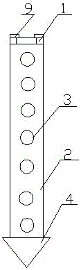
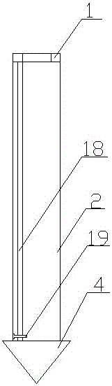
[0048] Embodiment 1: A grounding rod, including a connecting rod 2, a grounding rod 4 arranged on the lower part of the connecting rod 2 and a driving head arranged on the upper part of the connecting rod 2, and a drill bit is arranged at the end of the connecting rod 4, so that The outer diameter of the drill bit is greater than or equal to the outer diameter of the connecting rod 2, the outer wall of the connecting rod 2 is provided with a number of outward opening blind holes 3, and the connecting rod 2 is provided with a threading hole 18 passing through the blind hole 3 in the axial direction .

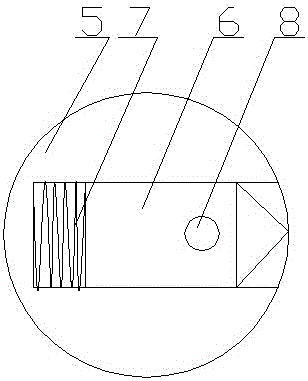
[0049] A fastener 6 is arranged in the blind hole 3 , and a compression spring 7 is arranged at the bottom of the fastener 6 .

[0050] The fastener 6 is provided with a through hole 8 matching with the threading hole 8 .

[0051] The lower part of the threading hole 18 is provided with a clamping module 19 for fixing the end of the tension rope, and the upper part of the thread...

Embodiment 2

[0055] Embodiment 2: The difference between it and Embodiment 1 is that scales are set on the tensioning rope 20 .

[0056] The blind hole 3 is a horizontal fan-shaped hole, and a horizontal fan-shaped fastener 16 is arranged in the horizontal fan-shaped hole.

[0057] Several holes 17 are set on the horizontal fan-shaped fastener 16 .

Embodiment 3

[0058] Embodiment 3: The difference from Embodiment 2 is that the outer wall of the fastener 6 is provided with a cutting edge.

[0059] The outer wall of the connecting rod 2 is provided with a copper plating layer of 1-2mm.

[0060] The surface of the fastener 6 is provided with a wire groove 22 for threading.

[0061] In this embodiment, a wire trough for easy threading is set, and when threading in the threading hole, it is convenient to guide the tension rope to enter the threading hole of the next fastener from the threading hole of the previous fastener, avoiding the The tight contact of the blind hole makes it difficult for the tension rope to pass through the threading hole, which reduces the threading time and improves the work efficiency.


PUM


Abstract

The invention discloses a ground rod, which comprises a connecting rod, a ground rod body and a drive head, wherein the ground rod body is arranged at the lower part of the connecting rod; the drive head is arranged at the upper part of the connecting rod; a drill bit is arranged at the end part of the ground rod body; the outer diameter of the drill bit is greater than or equal to that of the connecting rod; a plurality of outward open bind holes are formed in the outer wall of the connecting rod; and the connecting rod is provided with a threading hole which passes through the blind holes along the axial direction. By the methods of forming the blind holes in the connecting rod and arranging fasteners into the blind holes, the contact area of the connecting rod and surrounding soil can be increased; and a relatively good anti-theft effect can be obtained. A relatively small resistance value is obtained due to increase of the contact area, so that the conductive effect is relatively good. In a manner of a tension rope, recycling of a ground electrode can be facilitated, but can only be achieved by a fastening module disclosed by the invention; and the ground rod is low in cost and worthy of application and popularization.

Description

technical field [0001] The invention belongs to the technical field of substation equipment and devices, and in particular relates to a grounding rod and a using method thereof. Background technique [0002] Although the proportion of the grounding device in the entire investment of power transmission and transformation projects and major buildings is very small, the accidents caused by it are extremely alarming. It can be described as a "grid killer". Secondary equipment, such as DC, protection, communication and other equipment, then caused the expansion of accidents, some caused equipment damage, caused fires, some caused the complete shutdown of power plants and substations, and some even developed into serious system accidents. For example, a power plant in Sichuan once discharged a high potential into the main control room due to severe corrosion of the neutral point grounding wire of the transformer, causing multiple breakdowns and short circuits. No. 1 generator cau...

Claims


Application Information

Patent Timeline
Patent Type & Authority Applications(China)
IPC IPC(8): H01R4/66H01R43/00
CPCH01R4/66H01R43/00
Inventor 杨秋月刘夏王明铭李中长惠浩
Owner 国网河南省电力公司南召县供电公司
Why Eureka
Try Eureka