A wireless power transmission system resonance compensation method with arbitrary constant voltage output
A technology of wireless power transmission and compensation method, applied in the direction of circuit devices, electrical components, etc., can solve the problems of reducing the flexibility and economy of system design
- Summary
- Abstract
- Description
- Claims
- Application Information
AI Technical Summary
Problems solved by technology
Method used
Image
Examples
Embodiment 1
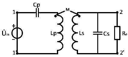
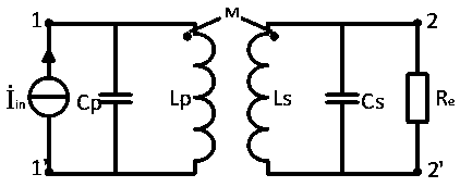
[0144] Embodiment 1: For a wireless power transmission system operating at a frequency of 100kHz, the self-inductance of the primary side of the magnetic coupling structure is 150uH, the self-inductance of the secondary side is 130uH, and the mutual inductance between the primary side and the secondary side is 30uH. It is 100V, and the optimization method is as follows:
[0145] When the output needs 100V, that is, the transformation ratio n is 1, use the parameters of the above formula (1) to design C p 21.1nF, C s is 25.3nF, at this time the output side can achieve the effect of constant voltage output 100V, the simulation results are as follows Figure 23 shown;
[0146] When the output needs 150V, that is, the transformation ratio n is 1.5, use the parameters of formula (1) to design C p 19.48nF, C s is 19.8nF, at this time the output side can achieve the effect of constant voltage output 150V, the simulation results are as follows Figure 24 shown;
[0147] When the...
PUM
 Abstract
Description
Claims
Application Information
 - R&D
- Intellectual Property
- Life Sciences
- Materials
- Tech Scout
- Unparalleled Data Quality
- Higher Quality Content
- 60% Fewer Hallucinations
Browse by: Latest US Patents, China's latest patents, Technical Efficacy Thesaurus, Application Domain, Technology Topic, Popular Technical Reports.
© 2025 PatSnap. All rights reserved.Legal|Privacy policy|Modern Slavery Act Transparency Statement|Sitemap|About US| Contact US: help@patsnap.com


