
a direct current generator

A technology of DC generator and synchronous motor, applied in synchronous generator and other directions, can solve the problems of poor reliability, high failure rate of rotating rectifier, difficulty in demagnetization and adjustment and control, and achieve the effect of improving reliability

Active Publication Date: 2018-08-14
CHINA PETROLEUM & CHEM CORP +1
View PDF5 Cites 0 Cited by
  • Summary
  • Abstract
  • Description
  • Claims
  • Application Information

AI Technical Summary

Problems solved by technology

[0005] Modern power systems generally use electrically excited synchronous motors as generators. Since synchronous generators use rotor excitation windings, static DC generators or rectifiers must provide excitation current to synchronous generators through brushes and slip rings, which has poor reliability.
The brushless excitation method of the existing AC exciter cancels the brushes and slip rings with poor reliability, but because the armature and rectifier are installed on the rotating shaft, the failure rate of the rotating rectifier is high, and it is very difficult to de-excite and adjust the control

Method used


Image

  • a direct current generator

Examples


Embodiment Construction

[0022] Embodiments of the present invention will be described in detail below with reference to the accompanying drawings.

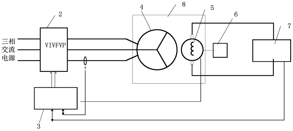
[0023] figure 1 A schematic structural diagram of a DC generator according to an embodiment of the present invention is shown.

[0024] refer to figure 1 , the DC generator 10 of the present invention includes a controller 3 , a converter 2 and a synchronous motor 8 .

[0025] The synchronous motor 8 includes a stator 4, a rotor 5, a prime mover 6, a field winding (not shown) mounted on the stator and an armature winding (not shown) mounted on the rotor, the prime mover 6 is mechanically connected to the rotor 5, Used to drive the rotation of the rotor 5.

[0026] In this embodiment, the potential of the rotor 5 is taken out through a brush slip ring (not shown) for connecting a DC load 7 .

[0027] The input terminal of the converter 2 is connected to the three-phase AC power supply, and the converter 2 converts the three-phase AC power output by th...


PUM


Abstract

The invention relates to a DC generator, comprising a controller, a transverter and a synchronous motor, wherein the synchronous motor comprises a stator winding and a rotor winding. The DC generator is characterized in that the transverter provides three-phase alternating current field current for the stator winding of the synchronous motor; the controller is used for controlling the transverter and the synchronous motor. The DC generator employs a stator as a field winding, and utilizes controllable three-phase alternating current as a field power supply, and a rotor as an armature winding; through adjusting the frequency, phase position and amplitude of alternating current, the rotor is allowed to generate DC power without a commutator; the DC generator possesses the advantages of static excitation and stable output voltage, and does not use a commutator.

Description

technical field [0001] The invention relates to a motor and its control technology, in particular to a DC generator. Background technique [0002] A DC generator is a machine that converts mechanical energy into DC electrical energy. It is mainly used as a DC power supply for DC motors, electrolysis, electroplating, electrosmelting, charging and excitation of alternators. [0003] A DC generator consists of a stationary part and a rotating part. The static part is called the stator, which includes the casing and the magnetic poles. The magnetic poles are of course used to generate a magnetic field; the rotating part is called the rotor, also known as the armature. The armature core is cylindrical, made of laminated silicon steel sheets, with grooves punched on the surface, and armature windings are placed in the grooves. The commutator is a structural feature of the DC motor. As the coil rotates, two fixed brushes are pressed against the commutator slides and connected to...

Claims


Application Information

Patent Timeline
Patent Type & Authority Patents(China)
IPC IPC(8): H02K19/26
Inventor 时振堂李志远贾鹏林秦文杰钱志红李君李琼
Owner CHINA PETROLEUM & CHEM CORP
Learn More