Solid state light source device, automotive lighting using same, image display device, and drive method for solid state light source device

A solid-state light source and driving method technology, which is applied in fixed lighting devices, light sources, headlights, etc., can solve the problems of inefficient concentrating and achieve high luminous efficiency

Active Publication Date: 2016-07-06
MAXELL HLDG LTD
View PDF13 Cites 10 Cited by
  • Summary
  • Abstract
  • Description
  • Claims
  • Application Information

AI Technical Summary

Problems solved by technology

[0003] As a light source for an image display device, an LED light source with high light output is generally a surface-emitting light source. When used in an illumination optical system, it is based on the e...

Method used


Image

  • Solid state light source device, automotive lighting using same, image display device, and drive method for solid state light source device
  • Solid state light source device, automotive lighting using same, image display device, and drive method for solid state light source device
  • Solid state light source device, automotive lighting using same, image display device, and drive method for solid state light source device

Examples


Embodiment 1

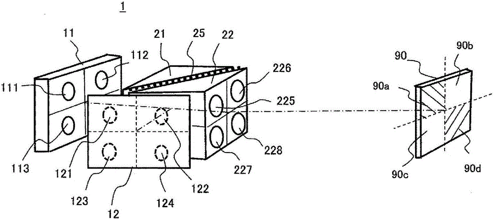
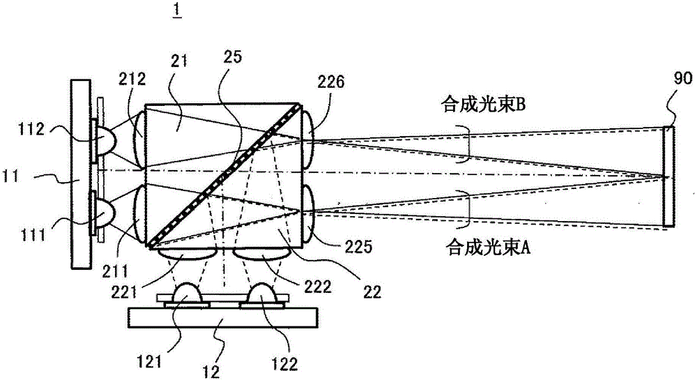
[0062] figure 1 and figure 2 is a configuration diagram showing a solid-state light source device as a first embodiment of the present invention, figure 1 is a stereogram, figure 2 is the floor plan. Hereinafter, the same reference numerals are assigned to components that perform the same functions.

[0063] The solid light source device 1 includes: a solid light source assembly 11 formed by arranging a plurality of solid light source units corresponding to green, and a solid light source assembly 12 formed by arranging a plurality of solid light source units corresponding to blue and red , and two multi-lens blocks 21 and 22 in which a plurality of multi-lens units are arranged in a matrix. The multi-lens blocks 21 and 22 have an isosceles right triangle cross-section, and the hypotenuses thereof are joined to each other with the dichroic filter 25 interposed therebetween. The solid-state light source assembly 11 and the solid-state light source assembly 12 are arrange...

Embodiment 2

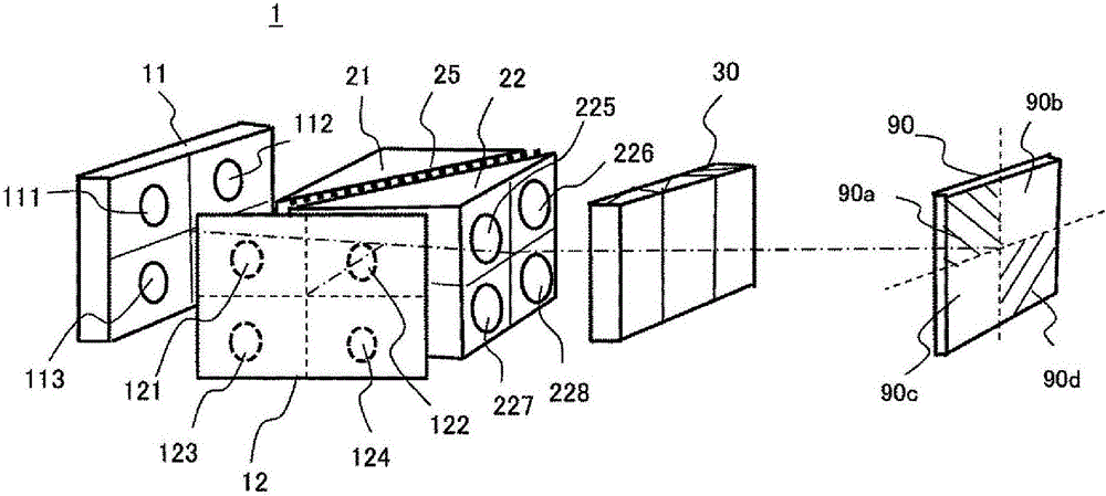
[0075] image 3 and Figure 4 is a configuration diagram showing a solid-state light source device as a second embodiment of the present invention, image 3 is a stereogram, Figure 4 is the floor plan. The difference from the above-mentioned Embodiment 1 is that the polarization conversion element 30 is arranged between the multi-lens block 22 and the light receiving part 90, so that the polarization direction of the outgoing light from the multi-lens block 22 is aligned and the light beam is superimposed on the light receiving part 90's structure.

[0076] For example, the green light beam emitted from the solid light source unit 111 of the solid light source assembly 11 is condensed by the multi-lens units 211 of the oppositely arranged multi-lens block 21, and is emitted from the multi-lens units of the corresponding multi-lens block 22. 225 zoom output. The luminous flux magnified and emitted from the multi-lens 225 enters the polarization conversion element 30 , and...

Embodiment 3

[0084] Figure 5 It is a plan view showing a solid-state light source device as a third embodiment of the present invention. This embodiment is in above-mentioned embodiment 2 ( Figure 4 ) in the structure, light shielding plates 41 and 42 are added on the exit side of the solid light source unit. By providing the shading plates 41, 42, it is possible to reduce return light (stray light) to the solid light source alone, ensure the life of the solid light source, and reduce adverse effects of stray light on the light source light.


PUM


Abstract

The invention provides a solid state light source device, automotive lighting using same, image display device, and drive method for the solid state light source device. The solid state light source device is provided with: N sets of solid state light source assemblies (N is an integer equal to or greater than 2) comprising a plurality of solid state light source cells arranged into matrix form; a multi-lens block having N inlet surfaces facing the N sets of solid state light source assemblies for letting in through a matrix of multi-lens cells the light emitted from each solid state light source cell and one exit surface for combining and sending out through the matrix of multi-lens cells the light entering from the N inlet surfaces; and a dichroic filter, which is selectively reflective or transmissive depending on the wavelength of the incident light, disposed inside the multi-lens block so as to be tilted with respect to each inlet surface. The proportion of electric power supplied to each solid state light source cell is controlled in order to control the light distribution characteristics and color temperature of the light emitted from the exit surface of the multi-lens block towards a light receiving part.

Description

technical field [0001] The present invention relates to a solid-state light source device such as a light-emitting diode (LED), a vehicle lamp using the same, an image display device, and a driving method for the solid-state light source device. Background technique [0002] In recent years, LED light sources and laser light sources with excellent power consumption efficiency and long product life have been used as light sources of image display devices or automobile headlights, which are one of optical application devices. Especially compared with the laser light source, the working environment (temperature, humidity) of the LED light source is less restricted, and the work is stable, and it is becoming the mainstream. [0003] As a light source for an image display device, an LED light source with high light output is generally a surface-emitting light source. When used in an illumination optical system, it is based on the etendue (also called etendue, Etendue=light emitti...

Claims


Application Information

Patent Timeline
IPC IPC(8): F21K9/20F21K2/00F21S8/12G03B21/14H01L33/00H05B37/02F21Y115/10
CPCF21S41/143F21S41/16F21S41/25F21S41/27F21S41/275F21S41/365F21S41/645H01L25/0753H01L2924/0002H01L2924/00F21S41/148F21S41/153
Inventor 平田浩二永野裕己山本将史瀬尾欣穗
Owner MAXELL HLDG LTD
Why Eureka
Try Eureka