A liquid impinging-stream reactor

A technology of impinging flow reactors and reactors, which is applied in the field of reactors to achieve the effects of saving reactor volume, reducing equipment investment, and reducing pressure drop

Active Publication Date: 2016-07-13
CHINA PETROLEUM & CHEM CORP +1
View PDF6 Cites 0 Cited by
  • Summary
  • Abstract
  • Description
  • Claims
  • Application Information

AI Technical Summary

Problems solved by technology

[0005] The technical problem to be solved by the present invention is to provide a liquid-phase impingement flow reactor for liquid-liquid mixing, which realizes fluid mixing through multiple impacts, and has a good microscopic mixing effect; the mixed liquid is pushed out of the impact area Flow, provide sufficient residence time for materials, realize cascade reaction, and achieve target conversion rate through flow channel and liquid flow rate design, overcome the shortcomings of current impingement flow reactors that cannot achieve high conversion rate through a single reactor

Method used


Image

  • A liquid impinging-stream reactor

Examples


Embodiment Construction

[0018] The liquid-phase impinging flow reactor of the present invention will be described in more detail below with reference to specific drawings.

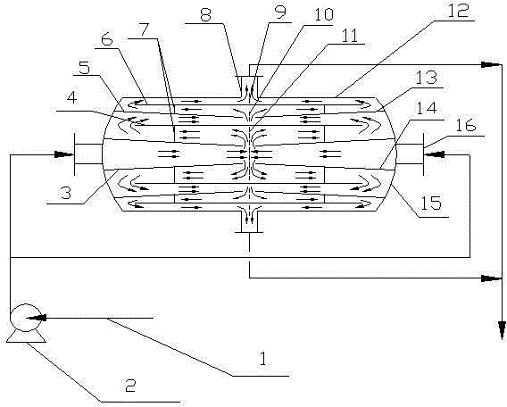
[0019] Such as figure 1 As shown, a liquid-phase impingement flow reactor for liquid-liquid multi-effect mixing of the present invention includes two parts: a reactor shell and a draft tube. The reactor shell is composed of a cylinder 12 and a head 15 . Two facing feed pipes 16 are arranged at the central position of the outer wall of the reactor shell head 15, and the first guide tubes 3 and 14 are connected to the inside of the reactor shell with the feed tubes. The first guide tube 3 and 14 are respectively frustum-shaped shells, and the two frustum-shaped shells are placed facing each other, and the axis of the first guide tube (frustum-shaped shell) coincides with the axis of the reactor. The thick end of the frustum-shaped shell is connected to the feed pipe, and the liquid is accelerated and mixed at the outlet of the th...


PUM


Abstract

An impinging-stream reactor used for liquid-liquid mixing is disclosed. The reactor comprises a reactor shell and draft tubes. The reactor shell comprises a cylinder and heads. Centers of the outsides of walls of two ends of the reactor shell are provided with two perpendicular opposite feeding pipes. The first draft tubes are formed through two circular truncated cone shells disposed in an opposite manner, axes of the shells and the reactor coincide, and a thicker end of each of the draft tubes is connected to the corresponding feeding pipe; the second draft tube is disposed outside the first draft tubes, is cylindric, and is connected to the heads or the first draft tubes, and the axis of the second draft tube and the axis of the reactor coincide; and so on, the reactor can include a plurality of groups of draft tubes. The reactor achieves a plurality of times of liquid impinging, provides sufficient residence time for materials, achieves stepped reactions, reaches the target conversion ratio through designing flowing paths and a liquid flow rate, and overcomes the disadvantage that an impinging-stream reactor at present cannot achieve a high conversion ration through a single reactor.

Description

technical field [0001] The invention relates to a reactor used in the field of petroleum and chemical production, in particular to an impingement flow reactor used for liquid-liquid reaction. Background technique [0002] In petroleum and chemical production, many processes are carried out in the liquid phase or in the phase state with the liquid as the continuous phase, and most of these processes also involve chemical reactions. Since the liquid belongs to the condensed matter system, molecular motion is greatly restricted. For processes that take place at the molecular scale, the microscopic mixing regime becomes very important. [0003] Impinging streams are a very effective method of achieving rapid mixing. It uses two high-speed fluids to collide with each other to form a highly turbulent impact zone in the reactor, which can effectively reduce the external resistance during the transfer process, promote mixing, and enhance mass and heat transfer. Impinging flow rea...

Claims


Application Information

Patent Timeline
Patent Type & Authority Applications(China)
IPC IPC(8): B01J14/00
Inventor 孟凡忠李欣齐慧敏张英薄德臣王红涛
Owner CHINA PETROLEUM & CHEM CORP
Why Eureka
Try Eureka