Method for mounting deep sea underwater heavy facility by using buoyancy blocks and hoisting and guiding dual-use cable

A buoyancy block and deep-sea technology, applied to cranes and other directions, can solve the problems of insufficient versatility and difficulty in greatly increasing the installation weight, and achieve the effect of reducing the requirement of compensation capacity

Active Publication Date: 2016-07-13
SINOPEC SHENGLI PETROLEUM ENG CO LTD DRILLING TECH RES INST
View PDF5 Cites 7 Cited by
  • Summary
  • Abstract
  • Description
  • Claims
  • Application Information

AI Technical Summary

Problems solved by technology

[0004] Domestically disclosed the installation equipment and method of deep sea subsea storage tanks (application number 2012100274318) which is suitable for the installation of deep sea tank structures, mainly using light liquid as an auxiliary, and lacks versatility; a buoyancy-adjustable underwater equipment auxiliary installation device and installation method (application No. 2014100482517) uses deep-sea buoyancy materials, and it is difficult to increase the installation weight significantly

Method used


Image

  • Method for mounting deep sea underwater heavy facility by using buoyancy blocks and hoisting and guiding dual-use cable
  • Method for mounting deep sea underwater heavy facility by using buoyancy blocks and hoisting and guiding dual-use cable

Examples


Embodiment 1

[0043] Example 1: Installation of joint module of subsea manifold and oil-gas separation

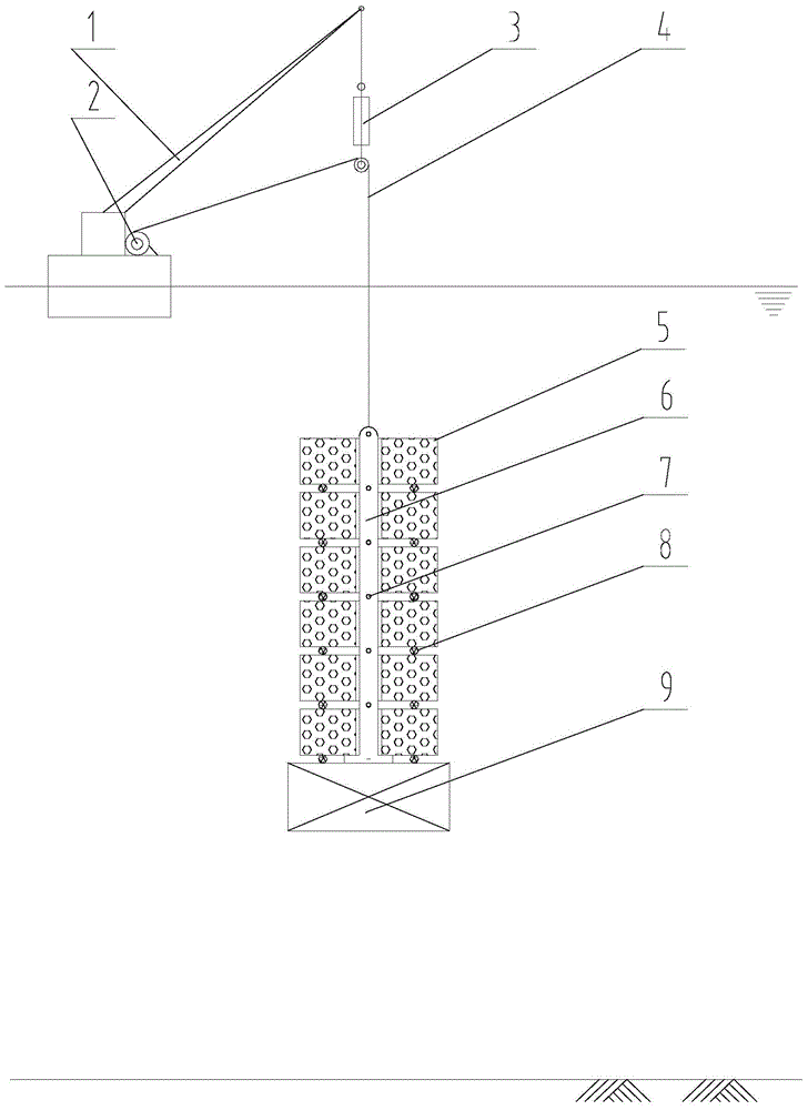
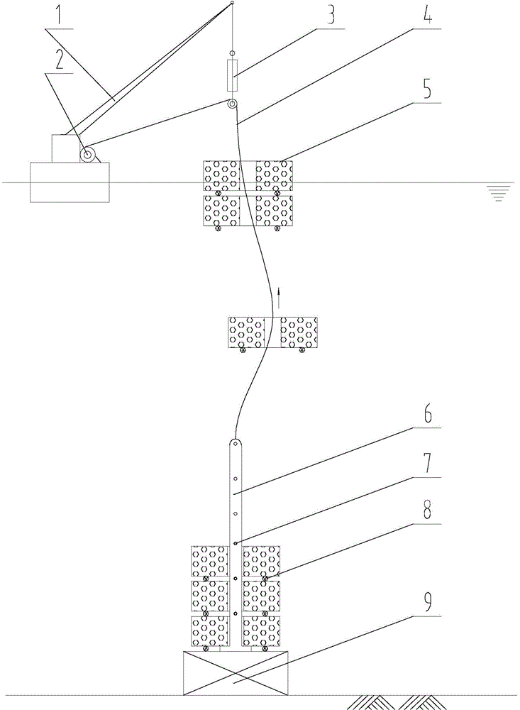
[0044] The water depth of the target area is 3000m. The self-weight of the module and accessories is 1321t, and the underwater self-weight is 1081t. Each deep sea buoyancy block used is 300m 3, with a dead weight of 201.5t and a remaining buoyancy of 106t, according to the calculation, 10 deep-sea buoyancy blocks are selected. The remaining weight of full immersion is 21t. As the water enters deeper, the remaining buoyancy provided by the deep-sea buoyancy block will decrease, and the remaining weight will increase to 53t. It is hoisted with a single cable with an allowable pulling force of 980KN. Connect all the equipment and components on the large barge with a total weight of 3436t. Use the auxiliary crane with a lifting capacity of 4500t to hoist the complete set of equipment into the water. , to accept 21t load. Remove the sling of the auxiliary crane, retract the winch and low...

Embodiment 2

[0045] Example 2: 100000m 3 Underwater tank installation

[0046] The water depth of the target sea area is 1500m. The main body of the storage tank is made of steel, with double walls, double roofs and no bottom. The maximum capacity of the storage tank is 100000m 3 , including the fixed weight of 18577t, the underwater weight of 14596t, and the underwater weight of 15311t after adding other auxiliary installation components; each deep-sea buoyancy block used is 300m 3 , with a dead weight of 201.5t and a remaining buoyancy of 106t, according to calculations, 144 deep-sea buoyancy blocks are selected. The remaining weight of full immersion is 47t. With the deepening of the water, the remaining buoyancy provided by the deep-sea buoyancy block under pressure will decrease, and the remaining weight will increase to 194t. Therefore, it is slightly different from the previous scheme: one is to use a double set of hoisting system, which consists of two Two systems with a single...


PUM


Abstract

The invention discloses a method for mounting a deep sea underwater heavy facility by using buoyancy blocks and a hoisting and guiding dual-use cable, and belongs to the technical field of sea engineering. The method uses the buoyancy blocks to carry and mitigate underground weight, so single-cable hoisting of the underwater facility with the weight far exceeding rated pulling force is realized, and requirements of the lifting ability of a major hanger and the compensation ability of a heave compensator are greatly reduced; and a recycling guiding cable, that is the hoisting and guiding dual-use cable, is constructed by using a hoisting cable to gradually recover the buoyancy blocks used in the construction process, so requirements of a too large separate buoyancy block on the release operating force and the resistance of the recovering guiding cable are avoided. The method subversively breaks the upper limit of present deep sea installation weight, is of great significance to construct underwater large facilities, and solves the installation problem of the deep sea underwater heavy facilities.

Description

technical field [0001] The invention belongs to the technical field of marine engineering, and in particular relates to a method for installing deep-sea underwater heavy facilities by using buoyancy blocks and dual-purpose suspension and guide cables. Background technique [0002] Limited by the lifting capacity and rope capacity of the floating crane, the maximum weight of a single unit installed on the deep seabed does not exceed several hundred tons at present, and there is no precedent for underwater installation of a structure with a self-weight of more than 1,000 tons in a sea area above 300m. Although the maximum lifting capacity of large-scale offshore floating cranes reaches tens of thousands of tons, the effective lifting range is usually similar to the height of the jib. For deep-sea installations, some operators temporarily modify the main hanger to increase the rope capacity of the winch and reduce the load. Rope pulleys, which also greatly reduce the maximum we...

Claims


Application Information

Patent Timeline
Patent Type & Authority Applications(China)
IPC IPC(8): B66C23/52
Inventor 徐松森张士华初新杰王宏安高慧商立社任红伟田凯傅忠尧崔希君
Owner SINOPEC SHENGLI PETROLEUM ENG CO LTD DRILLING TECH RES INST
Why Eureka
Try Eureka