
Wavelength control device for adjustable optical module, and method thereof

A dimming module and wavelength control technology, which is applied to lasers, laser components, electrical components, etc., can solve the problems of complex coefficient adjustment, long adjustment time, and large area occupation, and achieve good dynamic stability, good controllability, and fast time effect

Active Publication Date: 2016-07-13
XGIGA COMM TECH
View PDF6 Cites 7 Cited by
  • Summary
  • Abstract
  • Description
  • Claims
  • Application Information

AI Technical Summary

Problems solved by technology

[0003] But for the hardware method, for the dimmable module, a large number of op amps, resistors and capacitors, and even some MOS tubes are required, which occupies a large area and the coefficient debugging is complicated
However, the software method cannot make full use of the current input change value (ITUNE value), and whether it is a position type or an incremental type, the confirmation of the proportional coefficient, integral coefficient and differential coefficient is more troublesome, and the adjustment time may be longer for some wavelengths. , related to the initial setting value
Not only that, it is also sensitive to the external environment during the power-on stage, and some wavelengths will oscillate multiple times, resulting in longer wave locking time and wider dynamic stability range; a fixed coefficient cannot be very well adjusted for all wavelengths and control
Therefore, neither the hardware method nor the software method in the prior art can meet the wavelength control requirements of the tunable optical module.

Method used


Image

  • Wavelength control device for adjustable optical module, and method thereof
  • Wavelength control device for adjustable optical module, and method thereof
  • Wavelength control device for adjustable optical module, and method thereof

Examples


Embodiment Construction

[0027] The preferred embodiments of the present invention will be further described in detail below in conjunction with the accompanying drawings.

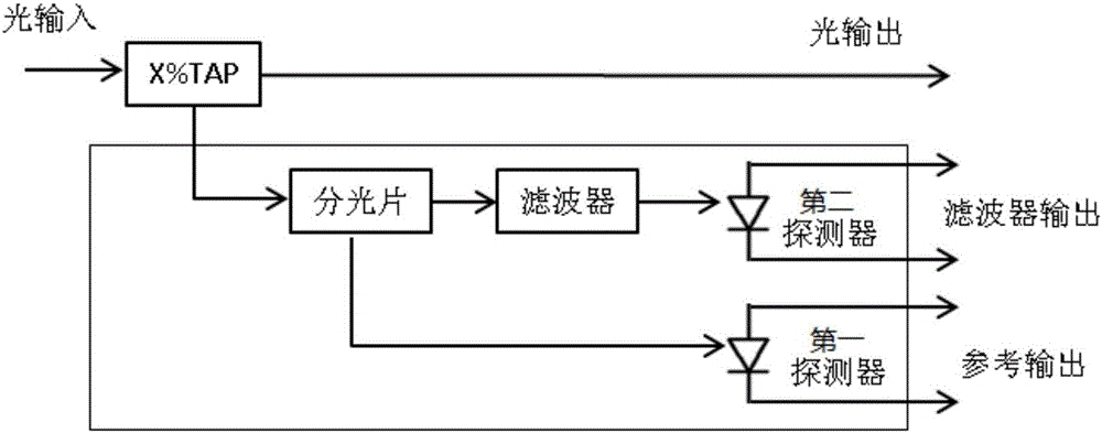
[0028] Such as figure 1 As shown, this example provides a wavelength control device for a tunable optical module, which includes: a splitter, a filter, a first detector, and a second detector. The optical signal of the tunable optical module is divided into the first An optical path and a second optical path, the first optical path is connected to the input end of the first detector, and the output end of the first detector outputs a reference signal; the second optical path is connected to the second optical path through a filter Detector, output standard signal.

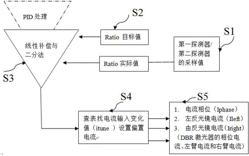
[0029] In this example, the second optical path is connected to the input end of the second detector through a filter, and the output end of the second detector is connected to the A / D sampling circuit to achieve a standard signal output after filtering; The ratio between ...


PUM


Abstract

The invention provides a wavelength control device for an adjustable optical module, and a method thereof. The wavelength control device comprises a beam splitter, a filter, a first detector and a second detector, wherein an optical signal of an adjustable optical module is divided into a first optical path and a second optical path through the beam splitter; the first optical path is connected with an input end of the first detector; an output end of the first detector outputs a reference signal; and the second optical path is connected with the second detector through the filter and outputs a standard signal. The wavelength control device for an adjustable optical module and the method thereof aim at and reasonably utilize the large data volume of a laser of the adjustable optical module to become efficient and controllable and have high dynamic stability by means of linear compensation, interpolation processing, dichotomy and other applications. Besides, all the wavelengths do not generate great vibration, and basically, each wavelength can approach to the locked state and then can achieve dynamic balance through 2-5 cycles so that the time is short and too many vibrations are not generated.

Description

Technical field [0001] The invention relates to a wavelength control device, in particular to a wavelength control device of a tunable optical module, and to a wavelength control method of the wavelength control device adopting the tunable optical module. Background technique [0002] Due to changes in conditions such as temperature and self-aging, the output optical power and wavelength of the laser of the tunable optical module will change. In order to make the optical transmitter output stable optical power or wavelength information, corresponding negative feedback measures must be adopted to control the light source The luminous power, bias current or temperature of the device, such as: APC (automatic power control) and AFC (automatic frequency control and wavelength control), conventional automatic control is divided into hardware PID and software PID to achieve, such as a simple hardware APC The description of (automatic power control) is as follows: the light transmitted f...

Claims


Application Information

Patent Timeline
IPC IPC(8): H01S3/102
CPCH01S3/102
Inventor 钱乐彬姜浩
Owner XGIGA COMM TECH
Learn More