
CAN bus transceiver

A CAN bus and transceiver technology, applied in the field of CAN bus transceivers, can solve the problems of high application cost of chip products and the inability of CAN bus transceivers to integrate chips, etc., and achieve the effect of reducing application costs

Active Publication Date: 2016-07-13
GIGADEVICE SEMICON (BEIJING) INC
View PDF4 Cites 2 Cited by
  • Summary
  • Abstract
  • Description
  • Claims
  • Application Information

AI Technical Summary

Problems solved by technology

[0004] In view of the above problems, the purpose of the embodiments of the present invention is to provide a CAN bus transceiver to solve the problem that the prior art CAN bus transceiver cannot be integrated into a chip under the standard CMOS process, and the application cost of the chip product is high.

Method used


Image

  • CAN bus transceiver
  • CAN bus transceiver
  • CAN bus transceiver

Examples


Embodiment 1

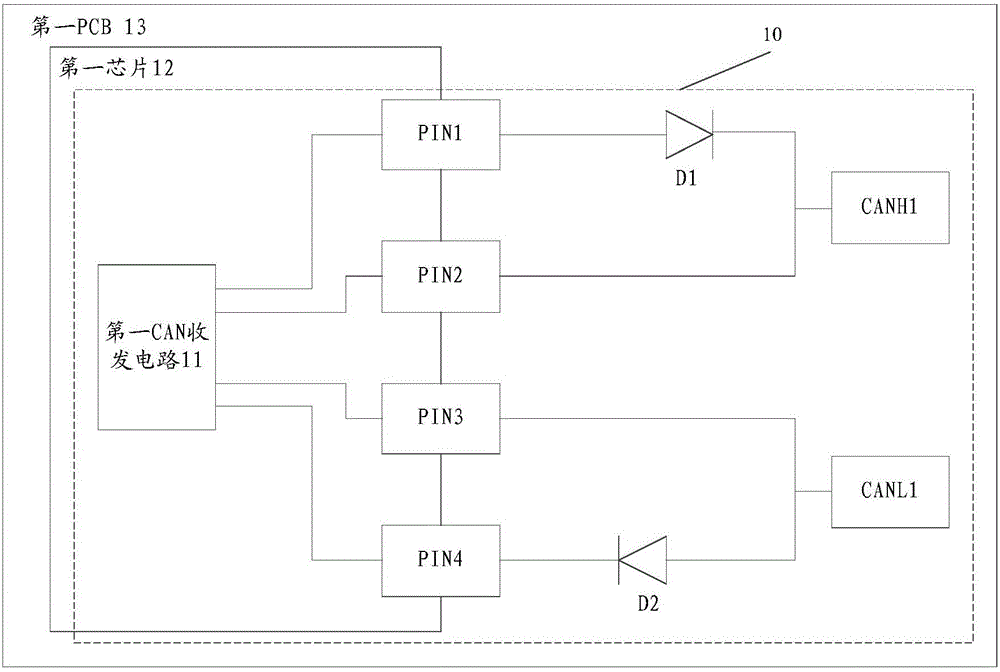
[0022] refer to figure 1 , shows a schematic structural diagram of the CAN bus transceiver according to Embodiment 1 of the present invention. refer to figure 1 The CAN bus transceiver 10 includes a first CAN transceiver circuit 11, a first diode D1, a second diode D2, a first CANH port CANH1 and a first CANL port CANL1, wherein the first CAN transceiver circuit 11 is integrated in In the first chip 12 under the standard CMOS process, the first CAN transceiver circuit 11 is respectively connected to the anode of the first diode D1, the first CANH port CANH1, the first CANL port CANL1 and the cathode of the second diode D2, The first CANH port CANH1 is connected to the cathode of the first diode D1, and the first CANL port CANL1 is connected to the anode of the second diode D2; the first chip 12, the first diode D1 and the second diode D2 are respectively arranged on the first PCB13.

[0023] Optionally, refer to figure 1 , the CAN bus transceiver 10 can also include the fi...

Embodiment 2

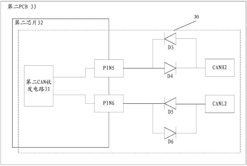
[0031] refer to image 3 , shows a schematic structural diagram of the CAN bus transceiver according to Embodiment 2 of the present invention. refer to image 3 , the CAN bus transceiver 30 includes a second CAN transceiver circuit 31, a third diode D3, a fourth diode D4, a fifth diode D5, a sixth diode D6, a second CANH port CANH2 and a second CANL port CANL2, wherein, the second CAN transceiver circuit 31 is integrated in the second chip 32 under the standard CMOS process, and the second CAN transceiver circuit 31 is respectively connected to the cathode of the third diode D3 and the anode of the fourth diode D4 1. The cathode of the fifth diode D5 is connected to the anode of the sixth diode D6, the second CANH port CANH2 is respectively connected to the anode of the third diode D3 and the cathode of the fourth diode D4, and the second CANL port CANL2 is respectively connected with the anode of the fifth diode D5 and the cathode of the sixth diode D6; the second chip 32, ...


PUM


Abstract

The embodiment of the invention provides a CAN bus transceiver, which comprises a first CAN transmitting and receiving circuit, a first diode, a second diode, a first CANH port and a first CANL port, wherein the first CAN transmitting and receiving circuit is integrated in a first chip in a standard CMOS technology; the first CAN transmitting and receiving circuit is respectively connected with the anode of the first diode, the first CANH port, the first CANL port and the cathode of the second diode; the first CANH port is connected with the cathode of the first diode; the first CANL port is connected with the anode of the second diode; and the first chip, the first diode and the second diode are arranged on a first PCB respectively. According to the embodiment of the invention, through adding at least two diodes on the PCB or through the existing at least two diodes on the PCB, the CAN bus transceiver is integrated in the chip in the standard CMOS technology, and the application cost of the chip product is reduced.

Description

technical field [0001] The invention relates to the technical field of communication, in particular to a CAN bus transceiver. Background technique [0002] When the traditional CAN (ControllerAreaNetwork, controller area network) bus transceiver is integrated with the chip, it is necessary to have a zener diode inside the chip, so that the CAN bus transceiver can be level-shifted and pass a large current through the zener diode. [0003] However, there are no zener diodes in chips such as MCU (Microcontroller Unit, micro control unit) under the standard CMOS (Complementary Metal Oxide Semiconductor) process, so the CAN bus transceiver of the prior art cannot be integrated into the standard CMOS process In the chip under the chip, when the chip product is applied in the system, it is necessary to connect a CAN bus transceiver on the PCB (Printed Circuit Board, printed circuit board), which increases the application cost of the chip product. Contents of the invention [000...

Claims


Application Information

Patent Timeline
IPC IPC(8): H04L12/40
CPCH04L12/40006H04L12/40032H04L2012/40215
Inventor 刘志
Owner GIGADEVICE SEMICON (BEIJING) INC
Learn More