Grinder with cooling function

A grinding wheel machine and functional technology, applied in the direction of grinding frame, other manufacturing equipment/tools, grinding machines, etc., can solve the problems of reducing tool sharpening efficiency, reducing work efficiency, raising and other problems, improving processing production efficiency, improving metal Mechanical properties, clear working principle

Inactive Publication Date: 2016-07-20
DANYANG ZHENGLIAN INTPROP OPERATIONS MANAGEMENT CO LTD
View PDF6 Cites 14 Cited by
  • Summary
  • Abstract
  • Description
  • Claims
  • Application Information

AI Technical Summary

Problems solved by technology

[0002] Grinder is one of the common grinding tools. The common grinders include double grinder and single grinder. In the skill training places of vocational colleges, grinder is an indispensable auxiliary processing equipment, especially in the training During the grinding of tools and knives, a large amount of heat is generated due to the friction between the workpiece and the grinding wheel. The heat generated makes the workpiece hot and even smokes, which is not conducive to the continuation of the grinding work. , which reduces work efficiency. In order to solve these problems, coolant is usually used to cool the workpiece during the grinding process so as to continue grinding. The sharp rise, in order to continue the handheld operation, the tool can only be moved back and forth between the cooling water tanks, which reduces the efficiency of tool sharpening and affects the processing production efficiency

Method used


Image

  • Grinder with cooling function

Examples


Embodiment Construction

[0015] The present invention will be further described below in conjunction with accompanying drawing:

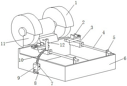
[0016] Such as figure 1 As shown, the grinder with cooling function includes a grinder composed of a grinder sheet 11 and a grinder cover 1; a water storage box 6 is provided below the grinder, and a fixed block 5 is provided at the front end of the water storage box 6 to fix A guide rod 4 is provided between the block 5 and the water storage box 6 rear ends, the guide rod 4 is provided with a hand-held handle 3, the hand-held handle 3 is provided with a workpiece fixture 2 and a water outlet nozzle 12, and the water outlet nozzle 12 is arranged on the workpiece holder 2 At the rear, a water outlet hole 8 is provided at the bottom of one side of the water storage box body 6, and a water pump body 9 is fixed above the water outlet hole 8 on the same side. 10 links to each other with outlet nozzle 12.

[0017] Such as figure 1 As shown, for a grinder with cooling function,...


PUM

PropertyMeasurementUnit
diameteraaaaaaaaaa
thicknessaaaaaaaaaa

Abstract

The invention discloses a grinder with the cooling function and belongs to the technical field of machining equipment. The grinder comprises a grinding machine which is composed of a grinding disc and a grinding machine housing, wherein a water storage tank body is arranged below the grinding machine; fixing blocks are arranged at the front end of the water storage tank body; a guide rod is arranged between each fixing block and the back end of the water storage tank body; a handheld handle is arranged on each guide rod; workpiece clamps and a water outlet nozzle are arranged on the corresponding handheld handles; the water outlet nozzle is formed behind one workpiece clamp; a water outlet is formed in the bottom end of one side of the water storage tank body; a water suction pump body is fixedly arranged above the water outlet on the same side; one end of the water suction pump body is connected with the water outlet; and the other end of the water suction pump body is connected with the water outlet nozzle. According to the grinder, the structure is simple, and the working principle is clear; with arrangement of a movable type clamp on the traditional grinder, the grinder has all the functions of the traditional grinder, the movable type clamp can also operated by replacing the traditional handheld type workpiece; and the design of a water outlet structure also ensures the cutter grinding process not to be influenced by burning hot of the workpiece, so that the metal mechanical properties of a ground part and the processing production efficiency are both improved.

Description

technical field [0001] The invention belongs to the technical field of machining equipment, and relates to a grinder, in particular to a grinder with a cooling function. Background technique [0002] Grinder is one of the common grinding tools. The common grinders include double grinder and single grinder. In the skill training places of vocational colleges, grinder is an indispensable auxiliary processing equipment, especially in the training During the grinding of tools and knives, a large amount of heat is generated due to the friction between the workpiece and the grinding wheel. The heat generated makes the workpiece hot and even smokes, which is not conducive to the continuation of the grinding work. , which reduces work efficiency. In order to solve these problems, coolant is usually used to cool the workpiece during the grinding process so as to continue grinding. The sharp rise, in order to continue the hand-held operation, the tool can only be moved back and forth...

Claims


Application Information

Patent Timeline
Patent Type & Authority Applications(China)
IPC IPC(8): B24B3/36B24B23/02B24B41/02B24B41/06B24B55/02
CPCB24B3/36B24B23/02B24B41/02B24B41/06B24B55/02
Inventor 杭康
Owner DANYANG ZHENGLIAN INTPROP OPERATIONS MANAGEMENT CO LTD
Why Eureka
Try Eureka