Briquetting machine for waste produced in machining

A briquetting machine and machining technology, applied in the direction of presses, manufacturing tools, etc., can solve the problems of large occupied space, inconvenient transportation, unsightly appearance, etc., achieve small occupied space, improve resource utilization, reduce machine The effect of processing costs

Active Publication Date: 2016-07-20
湖南省洪江市安达有限责任公司
View PDF5 Cites 29 Cited by
  • Summary
  • Abstract
  • Description
  • Claims
  • Application Information

AI Technical Summary

Problems solved by technology

Machining is a processing technology that removes materials through mechanical precise machining, and is an important production form in the machinery manufacturing industry; in the process of machining, metal waste, such as granular waste blocks or spiral chip belts, etc., may not necessarily appear. Scrap usually accounts for 5% to 10% of the weight of the metal material to be cut. The metal scrap can be recycled after being recycled and melted, while the granular or spiral metal scrap is generally loose, and it is not only unsanitary and unsightly to pile up. , and takes up a lot of space; at the same time, it is not convenient for transportation

Method used


Image

  • Briquetting machine for waste produced in machining
  • Briquetting machine for waste produced in machining

Examples


Embodiment

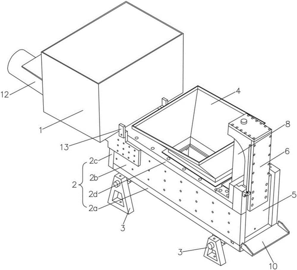
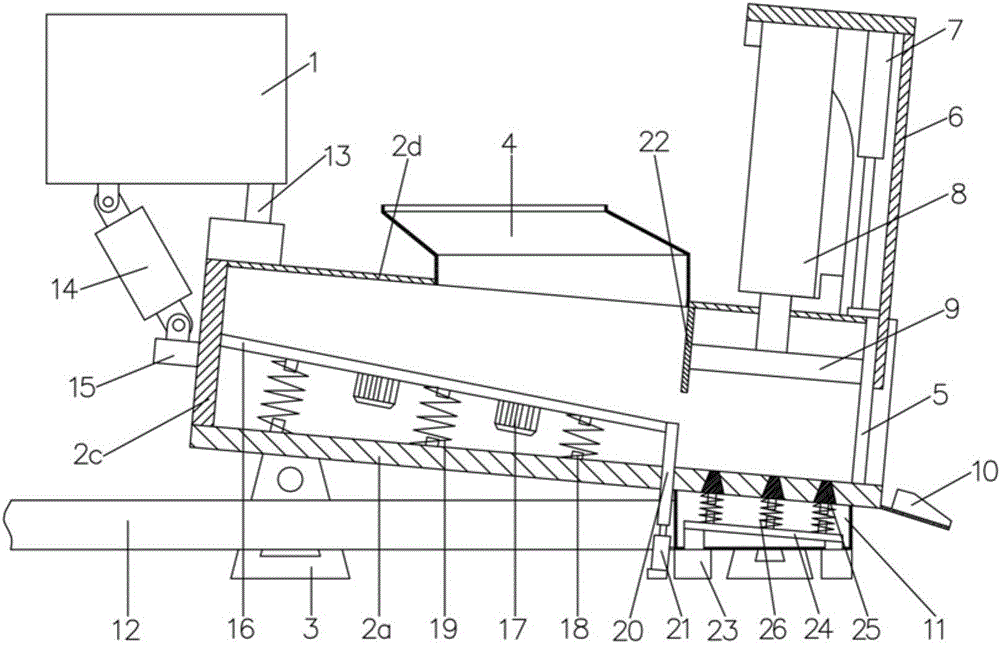
[0020] Example: see Figures 1 to 2 As shown, a machining waste briquetting machine includes a waste hopper 1, and one side of the waste hopper 1 is provided with an inclined rectangular cabinet body 2, and the rectangular cabinet body 2 is composed of a bottom plate 2a, a side plate 2b, a rear panel 2c and a top plate 2d, a number of machine feet 3 are fixed on the lower end surface of the bottom plate 2a, a feed hopper 4 is fixedly connected to the rear end of the top plate 2d; a valve 5 is plugged into the front side of the rectangular cabinet body 2, and the upper end of the valve 5 is fixedly connected to On the piston rod of the lifting cylinder 7, the lifting cylinder 7 is fixed on the oil cylinder fixing bracket 6, and the oil cylinder fixing bracket 6 is fixed on the rectangular cabinet body 2. In the oil cylinder fixing bracket 6, an extrusion cylinder 8 is fixed, and the piston of the extrusion cylinder 8 The rod is fixedly connected with a pressure plate 9, which i...


PUM


Abstract

The invention discloses a briquetting machine for waste produced in machining. An inclined rectangular cabinet body is arranged on one side of a waste hopper, and comprises a bottom plate, side plates, a rear plate and a top plate. A plurality of machine legs are fixed on the lower end surface of the bottom plate. A feeding hopper is fixedly connected to the rear end of the top plate. A valve is in plug-in connection with the front side of the rectangular cabinet body. The upper end of the valve is fixedly connected to a piston rod of a lifting cylinder. The lifting cylinder is fixed on a cylinder fixing bracket. The cylinder fixing bracket is fixed on the rectangular cabinet body. An extruding cylinder is fixed in the cylinder fixing bracket. A piston rod of the extruding cylinder is fixedly connected with a pressing plate. The pressing plate is in plug-in connection to the interior of the rectangular cabinet body and is abutted against the valve. A plurality of water outlets are formed in the bottom plate on the lower side of the pressing plate. A collect pan is fixedly connected to the lower end surface of the bottom plate. A drain pipe is fixedly connected to the collect pan. The metal waste produced in machining is compressed into blocks, so that the occupied space is reduced, and besides, the metal waste is conveyed to a smelting furnace to be melted conveniently, and a cutting fluid can be recovered.

Description

Technical field: [0001] The invention relates to the technical field of waste metal recycling equipment, and more specifically relates to a machining waste treatment device. Background technique: [0002] Manufacturing industry can directly reflect the productivity level of a country and is an important factor that distinguishes developing countries from developed countries. Machining is a processing technology that removes materials through mechanical precise machining, and is an important production form in the machinery manufacturing industry; in the process of machining, metal waste, such as granular waste blocks or spiral chip belts, etc., may not necessarily appear. Scrap usually accounts for 5% to 10% of the weight of the cut metal material. The metal scrap can be recycled after being recycled and melted, while the granular or spiral metal scrap is generally loose, and it is not only unhygienic and unsightly to pile up. , and takes up a lot of space; at the same time...

Claims


Application Information

Patent Timeline
Patent Type & Authority Applications(China)
IPC IPC(8): B30B9/32B30B15/00B30B15/30
CPCB30B9/327B30B15/30B30B15/0005
Inventor 王文庆
Owner 湖南省洪江市安达有限责任公司
Why Eureka
Try Eureka