
Pneumatic monorail crane

A monorail crane and track technology, applied in the field of monorail cranes, can solve the problems of exhaust gas pollution, unreliable braking, loud noise, etc., and achieve the effects of reliable working gas path, safe braking and long service life

Active Publication Date: 2016-07-20
淮北市中安矿机设备有限公司
View PDF8 Cites 2 Cited by
  • Summary
  • Abstract
  • Description
  • Claims
  • Application Information

AI Technical Summary

Problems solved by technology

[0003] Due to the different traction heads, its use is also different. For example, diesel engine or electric motor is used for traction, which has good flexibility and unlimited transportation distance. It can transport personnel, materials and equipment to any place needed, and has strong climbing ability. The maximum inclination angle of diesel locomotives can reach 30°, and that of battery locomotives can reach 15°. However, the exhaust gas emitted by diesel monorail cranes is polluted, smelly, and noisy. Battery locomotives require power supply, which affects underground use, and the above-mentioned power has costs in underground mines. Too high, underground safety requires explosion-proof, unreliable braking and many other problems need to be solved
[0004] Pneumatic monorail cranes work with the energy provided by the underground air pressure pipe. Since the underground air source follows the roadway, the power is available everywhere. However, there is a problem of stability in the pressure provided by the air pressure pipe. The existing pneumatic monorail The starting pressure of the crane needs to be 4KG or above, which limits the promotion of pneumatic monorail cranes, and the existing pneumatic monorail cranes still lose control or control failure (auxiliary holding Aging of brake springs) and many other problems such as the maximum inclination angle is too low (15° or lower)

Method used


Image

  • Pneumatic monorail crane
  • Pneumatic monorail crane

Examples


Embodiment Construction

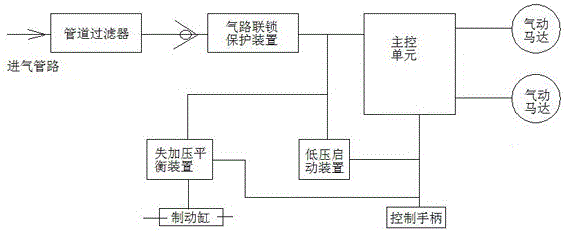
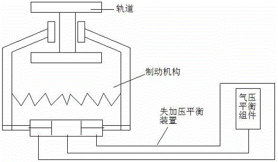
[0017] The existing pneumatic monorail cranes are mainly produced by German technology or Czech technology. Since the pneumatic monorail crane does not need power supply, has no pollution, and there is an underground gas source, it is a product worth promoting in terms of cost and safety. Existing technologies, mainly the leading technologies and products led by the above-mentioned countries, have many problems. Therefore, the present invention provides a pneumatic monorail crane, such as figure 1 , 2 As shown, it includes a track installed on the top of the roadway, a traction head installed on the track and connected in sequence, a number of lifting devices, and a braking mechanism. Air pipeline, one end of the air intake pipeline is connected to the air source, and the other end is sequentially installed with a pipeline filter, a one-way valve, and an air circuit interlock protection device. The air circuit interlock protection device outputs the air source to the main cont...


PUM


Abstract

The invention discloses a pneumatic monorail crane. A traction machine head comprises a machine head frame and an air inlet pipeline mounted in the machine head frame; one end of the air inlet pipeline is connected with an air source, and a pipeline filter, a one-way valve and an air path interlocking protection device are sequentially mounted at the other end of the air inlet pipeline; the air path interlocking protection device outputs the air source to a master control unit, a pressure loss and pressurizing balance device and a low-pressure starting device, and the master control unit is in control connection with two pneumatic motors, the pressure loss and pressurizing balance device, the low-pressure starting device, and a control handle, wherein the two pneumatic motors, the pressure loss and pressurizing balance device and the low-pressure starting device are mounted in the machine head frame, and the control handle is located outside the machine head frame and connected through a pipeline; and the pressure loss and pressurizing balance device is connected with a brake cylinder of a brake mechanism, and the pressure loss and pressurizing balance device and the low-pressure starting device each comprise a pneumatic balance assembly. Any fluctuation of the air source pressure ranging from 0.25 MP to 0.8 MP is met, and the pneumatic monorail crane completely meets the underground complex working condition; and the pneumatic monorail crane has functions of low-pressure starting, wide-pressure work, pressure loss protection, strong climbing energy and the like and is safe, reliable and long in service life.

Description

technical field [0001] The invention relates to a monorail crane, in particular to a pneumatic monorail crane. Background technique [0002] The monorail crane is a kind of crane tool. It uses a special I-beam hanging above the roadway as the track, and the hanging vehicles with various functions are connected into a train group, and the traction equipment is used to pull the system running along the track. Its traction power can be provided by wire rope, diesel engine, battery or pneumatic device. Because the monorail crane has a small section of the machine and a high utilization rate of the section space of the roadway, it is used for continuous non-reloading transportation of horizontal and inclined roadways. The transport load is not limited by the floor conditions and can run on various vertical curves, flat curves and complex curves. , Auxiliary transportation from the mining area yard to the working face without reloading, auxiliary transportation that connects the ...

Claims


Application Information

Patent Timeline
Patent Type & Authority Applications(China)
IPC IPC(8): B66C11/00B66C9/14
CPCB66C9/14B66C11/00
Inventor 周庆府周宝宝蒋文建张孝朗
Owner 淮北市中安矿机设备有限公司
Learn More