Eureka AIR delivers breakthrough ideas for toughest innovation challenges, trusted by R&D personnel around the world.

Recovery system and recovery method for converter gas

A converter gas and recovery system technology, applied in the direction of manufacturing converters, etc., can solve the problem of lack of comparability, and achieve the effects of less recovery, avoiding waste, and improving calorific value

Active Publication Date: 2016-07-20
ANGANG STEEL CO LTD
View PDF3 Cites 8 Cited by
  • Summary
  • Abstract
  • Description
  • Claims
  • Application Information

AI Technical Summary

Problems solved by technology

However, in actual production, a separate comparison of "converter gas recovery per ton of steel (m 3 / t)” is not directly comparable, it needs to be considered together with the calorific value of recovered gas

Method used


Image

  • Recovery system and recovery method for converter gas
  • Recovery system and recovery method for converter gas

Examples


Embodiment

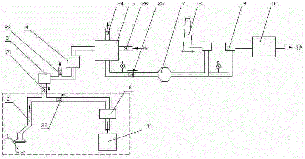
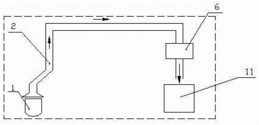
[0054] For a 158t converter in a factory, the maximum amount of molten iron charged is 155 tons / furnace, the temperature before and after the flue gas enters and exits the vaporization cooling flue 2 is around 1550°C and 750°C, the average recovery of steam is 59-86kg / t, and the flue gas contains Dust amount 67mg / m 3 Around, converter gas recovery volume maintained at 83m 3 / t±3m 3 , the calorific value of converter gas is 6.7MJ / m 3 Left and right, converter gas CO, CO 2 The contents are about 45%~65%, 20%~25%, respectively, and the restrictive conditions for converter gas recovery are CO≥35%, O 2 <2%, the recovery time is approximately 11.5 minutes from the 4th minute to the 15.5th minute of blowing, and the dust removal system adopts the OG method. The utilization rate of CDQ powder is calculated as 50%.

[0055] Such as figure 1 As shown, the method in which the converter gas recovery system is directly installed at the outlet end of the flue 2 of the vaporization co...


PUM


Abstract

The invention discloses a recovery system and recovery method for converter gas. The recovery system for the converter gas is composed of an evaporative cooling section flue, a dust collector, a gas enriching device, a medium converter gas storage tank, a N2 pipeline, a valve A, a valve B, a valve C, a valve D, a valve E, a valve F, an induced draft fan, a diffusion tower, a switching station and a converter gas recovery cabinet. The recovery system for the converter gas is installed at the outlet end of an evaporative cooling section flue of an original converter gas recovery system. The technical process comprises the steps that the high-temperature converter gas coming out of the evaporative cooling section flue enters the dust collector and then is guided into the gas enriching device for the gasification reaction, 80% or more of CO2 in the converter gas is converted into CO, the enriched converter gas sequentially enters the switching station and the converter gas recovery cabinet under the suction of the induced draft fan after buffering and pressure stabilizing are conducted on the enriched converter gas through the medium converter gas storage tank, and then recovery of the converter gas is completed. The recovery system and recovery method for the converter gas have the effects that the heat value of gas recovered from per ton of steel can be increased, the amount of converter gas recovered from per ton of steel is improved, waste and atmospheric pollution which are caused by diffusion are avoided, and the steelmaking cost is reduced.

Description

technical field [0001] The invention belongs to the technical field of energy saving and emission reduction, and in particular relates to a converter gas recovery system and recovery method capable of enlarging the recovery amount of converter gas per ton of steel by means of enrichment and greatly increasing the calorific value of recovered gas. Background technique [0002] Converter gas is an important secondary energy for iron and steel enterprises, and converter gas recovery accounts for 80%-90% of the energy recovery in the entire converter process. Improving the level of recovery and utilization of converter gas is an important means to realize negative energy steelmaking. At present, the recovery and utilization levels of converter gas in iron and steel enterprises vary greatly. Many iron and steel enterprises have a small amount of average recovery of converter gas, low calorific value, few users, and the release of converter gas. The calculation shows that the max...

Claims


Application Information

Patent Timeline
Patent Type & Authority Applications(China)
IPC IPC(8): C21C5/40
Inventor 刘德军郝博王飞赵爱华马光宇王忠润王萍
Owner ANGANG STEEL CO LTD
Why Eureka
Eureka Blog
Learn More