Burner ignition device and high-energy igniter

An ignition device and burner technology, which is applied in the direction of combustion ignition, safety device of combustion chamber, combustion chamber, etc., can solve problems such as difficulty in ignition, fire off, flameout, poor flame stability, etc., to improve the success rate of ignition and flame The effect of stability

Inactive Publication Date: 2016-07-20
SHANGHAI QIYAO THERMAL ENERGY ENG CO LTD
View PDF11 Cites 13 Cited by
  • Summary
  • Abstract
  • Description
  • Claims
  • Application Information

AI Technical Summary

Problems solved by technology

However, most advanced entrained entrained gasifiers need to be ignited under a certain pressure (such as 0.3-1MPa), which is difficult to ignite and has poor flame stability. Especially in the process of continuing to heat up and increase pressure, it is prone to flameout and flameout.
Moreover, the monitoring of the flame condition only depends on the flame detection signal, and there is a possibility of false detection

Method used


Image

  • Burner ignition device and high-energy igniter
  • Burner ignition device and high-energy igniter

Examples


Embodiment Construction

[0019] In the following description, numerous specific details are given in order to provide a more thorough understanding of the present invention. It will be apparent, however, to one skilled in the art that embodiments of the invention may be practiced without one or more of these details. In other examples, in order to avoid confusion with the embodiments of the present invention, some technical features known in the art are not described.

[0020] In order to thoroughly understand the embodiments of the present invention, the detailed structure will be set forth in the following description. Obviously, the practice of the embodiments of the invention is not limited to specific details familiar to those skilled in the art. Preferred embodiments of the present invention are described in detail below, however, the present invention may have other embodiments besides these detailed descriptions.

[0021] According to one aspect of the present invention, a burner ignition de...


PUM


Abstract

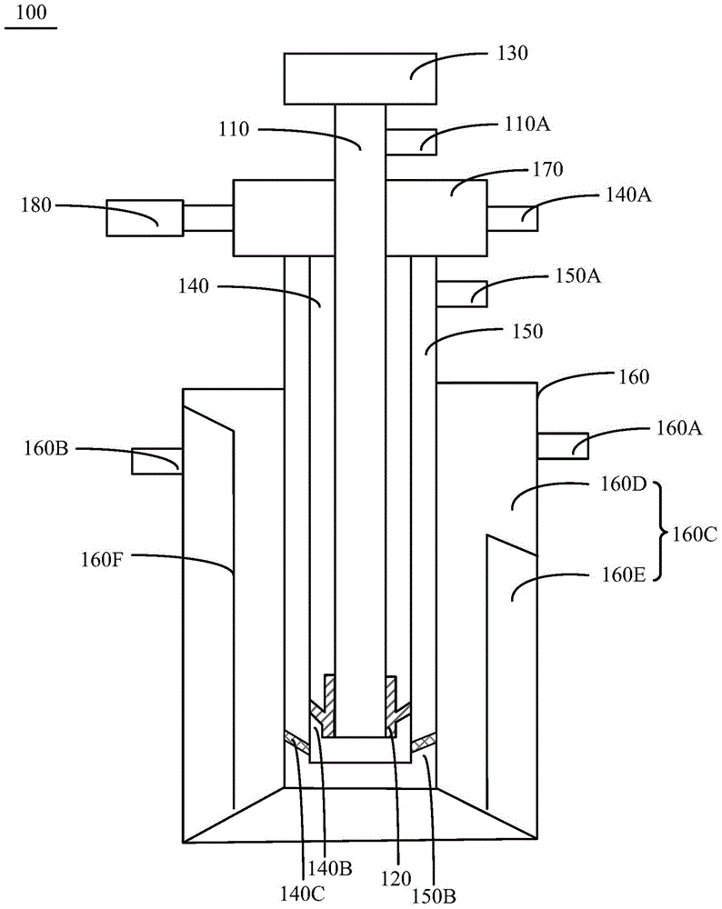
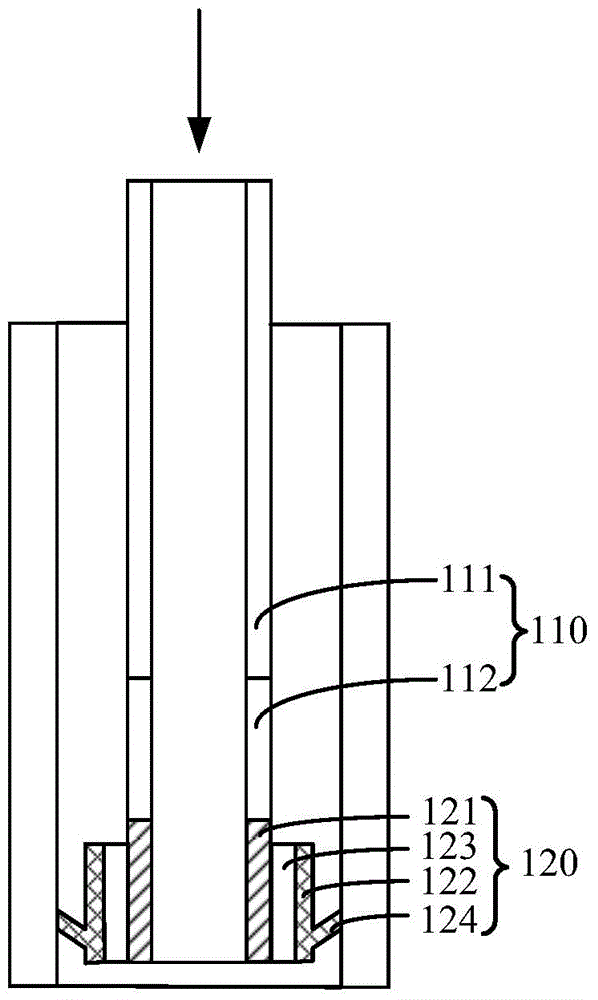
The invention discloses a burner ignition device and a high-energy igniter. The burner ignition device comprises a hollow pipe, the high-energy igniter, a flame monitor, a fuel conveying pipe, a fuel inlet, a combustion improver conveying pipe, a combustion improver inlet and a cooling water conveying pipe. The high-energy igniter is arranged at a first end of the hollow pipe, and includes an anode, a cathode arranged out of the anode and an insulation layer from insulating the anode from the cathode; and a hollow structure communicated with the hollow pipe is formed in middle of the anode. The flame monitor is arranged at a second end of the hollow pipe for monitoring the flame conditions through the hollow pipe and the hollow structure. The fuel conveying pipe coats the hollow pipe and the cathode, and is at least partially separated from the hollow part. The combustion improver conveying pipe coats the fuel conveying pipe, and is at least partially separated from the fuel conveying pipe. The cooling water conveying pipe coats the combustion improver conveying pipe, and two end parts are closed; and the cooling water conveying pipe includes a water inlet, a cooling water circulating channel and a water return port. The device can improve the ignition success rate.

Description

technical field [0001] The invention relates to the technical field of gasification furnace structure, in particular to a high-energy igniter and a burner ignition device with the high-energy igniter. Background technique [0002] In the field of traditional coal chemical industry, entrained bed technology is an advanced coal gasification technology, mainly including coal water slurry gasification, pulverized coal gasification, fluidized bed gasification, etc. Among them, in the entrained bed technology, the gasifier is a very important equipment. Coal powder / coal water slurry and oxygen react at high temperature in the gasifier to generate synthesis gas, which is then synthesized in the downstream conversion system. Therefore, the safe and stable operation of the gasifier is one of the key factors in the gasification process. In the initial stage of gasification start-up, it is necessary to complete the ignition under the set process conditions. Traditional ignition devi...

Claims


Application Information

Patent Timeline
Patent Type & Authority Applications(China)
IPC IPC(8): F23Q3/00F23M11/04
Inventor 匡建平张世程揭涛赵子通刘思远眭向荣
Owner SHANGHAI QIYAO THERMAL ENERGY ENG CO LTD
Why Eureka
Try Eureka