Stimulated Brillouin effect-based differential temperature sensor

A technology of stimulated Brillouin and temperature sensors, which is applied in the direction of physical/chemical change thermometers, thermometers, instruments, etc., can solve the problems of limited sensing distance, limited spatial resolution, reduced frequency resolution, etc., to achieve The effect of high frequency resolution, high spatial resolution, and long measurement distance sensing

Active Publication Date: 2016-07-20
BEIJING UNIV OF POSTS & TELECOMM
View PDF7 Cites 13 Cited by
  • Summary
  • Abstract
  • Description
  • Claims
  • Application Information

AI Technical Summary

Problems solved by technology

[0006] In the traditional BOTDA system, due to the limitation of phonon relaxation, the pulse width cannot be smaller than the phonon relaxation time, otherwise the phonon will not reach a steady state, resulting in a decrease in signal-to-noise ratio, broadening of the Brillouin gain spectrum, and frequency The resolution is reduced, which greatly limits the further improvement of the spatial resolution
The pre-pumping method solves the limitation of phonon relaxation to a certain extent by pre-pumping a pulse in advance, but the sensing distance is limited, and the long-distance sensing will cause the Brillouin gain of the pulse base to be greater than the pulse itself. gain
In the dark pulse method, almost no phonons are excite

Method used


Image

  • Stimulated Brillouin effect-based differential temperature sensor
  • Stimulated Brillouin effect-based differential temperature sensor
  • Stimulated Brillouin effect-based differential temperature sensor

Examples


Example Embodiment

[0038] In order to make the objectives, technical solutions, and advantages of the embodiments of the present invention clearer, the technical solutions in the embodiments of the present invention will be described clearly and completely in conjunction with the accompanying drawings in the embodiments of the present invention. Obviously, the described embodiments It is a part of the embodiments of the present invention, not all the embodiments. Based on the embodiments of the present invention, all other embodiments obtained by those of ordinary skill in the art without creative work shall fall within the protection scope of the present invention.
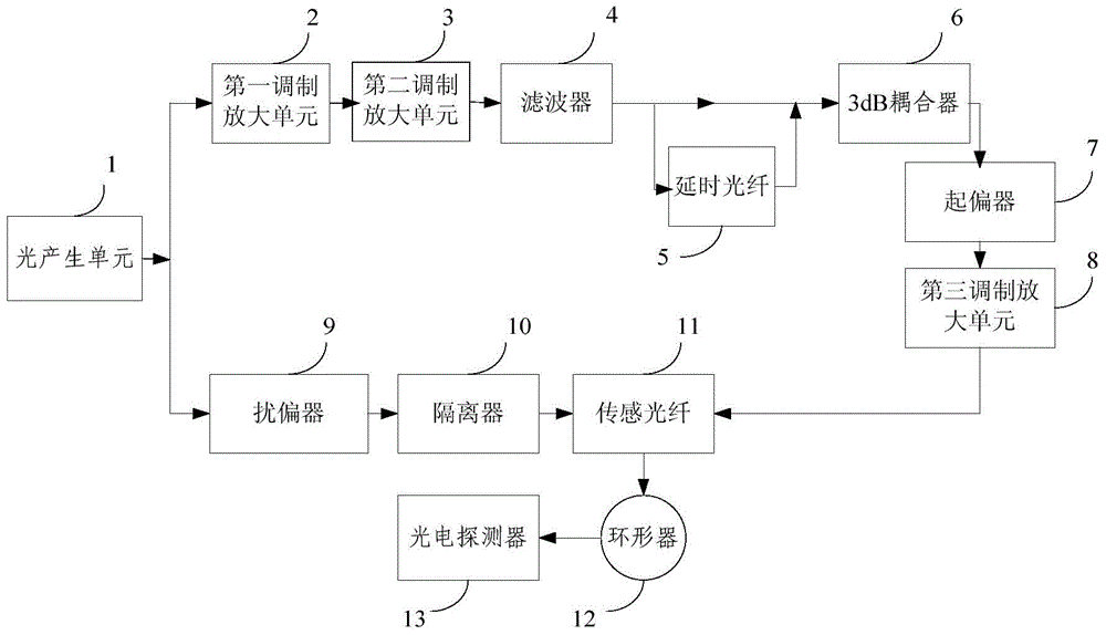
[0039] figure 1 The structure block diagram of a differential temperature sensor based on stimulated Brillouin effect proposed for the present invention, such as figure 1 Shown, including:

[0040] Light generating unit 1, first modulation amplifying unit 2, second modulation amplifying unit 3, filter 4, delay fiber 5, 3dB coupler 6, po...


PUM


Abstract

The present invention provides a stimulated Brillouin effect-based differential temperature sensor. The continuous light generated by a light generating unit is subjected to a first modulation amplifier unit to obtain a signal containing the Stokes light and the anti-Stokes light. After that, the signal is subjected to a second modulation amplifier unit to generate a phase modulated signal. The modulated signal is subjected to a filter, so that the Stokes light and the anti-Stokes light are filtered out. The Stokes light passes through a delay optical fiber to be integrated with the anti-Stokes light as one path of optical signals through a 3 dB coupler. The path of optical signals is subjected to a polarizer, so that the polarized light can be extracted. The extracted polarized light is subjected to a third modulation amplifier unit to obtain the pumped pulse light. The pumped pulse light is injected into the initial end of a sensing optical fiber. The detection light of the other path is infiltrated through the tail end of the sensing optical fiber via a scrambler instrument and an isolator. Inside the optical fiber, the detection light forms a circulator together with the pumped pulse light under the stimulated Brillouin effect, and then is converted into an electric signal through a photoelectric detector. According to the technical scheme of the invention, the temperature resolution and the sensing distance are higher on the premise that the high spatial resolution is realized.

Description

technical field [0001] The invention relates to the technical field of temperature or stress sensors, in particular to a differential temperature sensor based on the stimulated Brillouin effect. Background technique [0002] The distributed optical fiber temperature and stress sensing system based on the stimulated Brillouin effect uses light waves as sensing signals and optical fibers as the transmission medium to sense and detect external measured temperature or stress signals. It not only has the advantages of general optical fiber sensors, Moreover, the continuous distribution information of temperature or stress with time and space can be obtained at the same time. Because the optical fiber itself has no electricity, small size, light weight, easy bending, anti-electromagnetic interference, and good anti-radiation performance, it is especially suitable for use in harsh environments such as flammable, explosive, and strong electromagnetic interference, making it suitable...

Claims


Application Information

Patent Timeline
IPC IPC(8): G01K11/32G01K11/322
Inventor 洪小斌林文桥伍剑郭宏翔李岩左勇邱吉芳李蔚林金桐
Owner BEIJING UNIV OF POSTS & TELECOMM
Why Eureka
Try Eureka