Riser forming machine

A molding machine and mold technology, applied to casting molding equipment, casting molds, cores, etc., can solve problems such as waste of manpower, achieve the effects of reducing labor intensity, turning over smoothly, and avoiding difficult demoulding

Inactive Publication Date: 2016-07-27
NANJING NINGJINYAO MACHINERY CO LTD
View PDF10 Cites 7 Cited by
  • Summary
  • Abstract
  • Description
  • Claims
  • Application Information

AI Technical Summary

Problems solved by technology

[0003] Aiming at the above-mentioned shortcomings, the present invention designs a riser forming machine, which is equipped with two sets of stirring devices in the slurry tank, which can fully make the mixture roll upwards as a whole so as to achieve the effect of no dead corner storage and uniform mixing. Four nylon hammers are designed in the left and right directions of the mold, which are controlled by the rotating cylinder, so as to hit the mold from four directions at the same time. The riser is not easy to demold and waste manpower. The fo

Method used


Image

  • Riser forming machine
  • Riser forming machine
  • Riser forming machine

Examples


Embodiment Construction

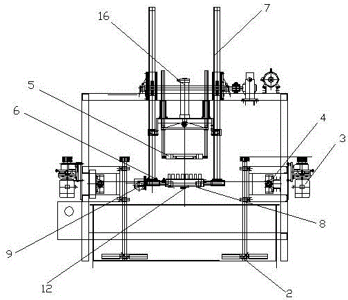
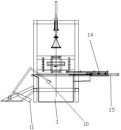
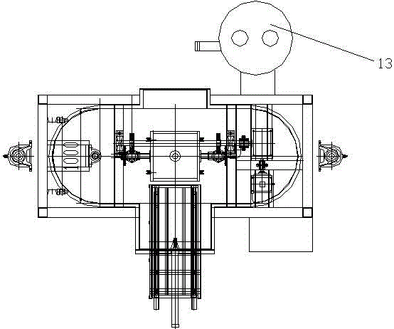
[0020] The present invention will be described in detail below with reference to the accompanying drawings and in combination with embodiments.

[0021] Such as figure 1 , figure 2 and image 3 A riser forming machine shown in and includes: a slurry tank 1, which is provided with two sets of stirring devices 2 with opposite stirring directions inside, and the stirring device is controlled by a rotating cylinder 4 and a reducer 3; The bar ascending shaft 7 is arranged on the upper side of the slurry tank 1, and slides up and down along the rack ascending shaft. The mold includes an inner mold 6 and an outer mold 5, and four nylon hammers 8 are arranged on the outer periphery of the inner mold, and the mold is provided with air extraction holes. A sliding track is provided below, the inner mold is turned over by the rotary cylinder 9, and the outer mold is controlled by the outer mold cylinder 16; the scraping device is arranged between the slurry pool and the mould, and the ...


PUM


Abstract

The invention discloses a riser forming machine which comprises a slurry tank, a die, a scraping device and a vacuum absorbing device. Two stirring devices opposite in stirring direction are arranged in the slurry tank. The die is arranged on the upper side of the slurry tank through a rack elevating shaft and slides along the rack elevating shaft vertically. The die comprises an inner die body and an outer die body. Four hammers are arranged on the periphery of the inner die body. The die is provided with an exhausting hole. The scraping device is arranged between the slurry tank and the die and comprises a brush oil cylinder, a stainless steel roller and a brush. The vacuum absorbing device comprises a vacuum box and a vacuum settling tank. The vacuum settling tank is provided with a gas inlet hole and a sewage draining opening. The gas inlet hole is connected with the exhausting hole of the die through a hose. The riser forming machine enables whole mixed materials to be turned over upwards, so that the effects of dead-angle-free material storage and uniform mixing are achieved. By means of automatic die releasing, the defects that due to the fact that a die is hammered manually, a riser can not be released from the die easily, and manpower is wasted are overcome, the inner wall and the outer surface of the produced riser are smooth, and the quality and the working efficiency of the riser are improved.

Description

technical field [0001] The invention relates to the field of riser casting and molding, in particular to a riser forming machine. Background technique [0002] The ordinary riser forming machine will cause different heat generation of risers in batches due to uneven mixing of various raw materials during molding, resulting in defective castings and waste products; ordinary riser forming machines are formed one by one during molding , thus wasting a lot of labor resources; ordinary riser forming machine will cause the appearance of the riser to be rough because the mold has no outer mold when forming, thus affecting the quality of the riser; the traditional method of making risers per shift is 400-700 pieces A lot of social resources such as electricity and manpower are wasted. Contents of the invention [0003] Aiming at the above-mentioned shortcomings, the present invention designs a riser forming machine, which is equipped with two sets of stirring devices in the slurr...

Claims


Application Information

Patent Timeline
IPC IPC(8): B22C9/08
CPCB22C9/088
Inventor 汪贤斌王玉珍
Owner NANJING NINGJINYAO MACHINERY CO LTD
Why Eureka
Try Eureka