A 3D metal printing system and method
A printing system, metal technology, applied in the field of metal printing, to achieve the effect of reducing the difficulty of control and flexible control
- Summary
- Abstract
- Description
- Claims
- Application Information
AI Technical Summary
Problems solved by technology
Method used
Image
Examples
Embodiment 1
[0059] Example 1: Printing metal particles
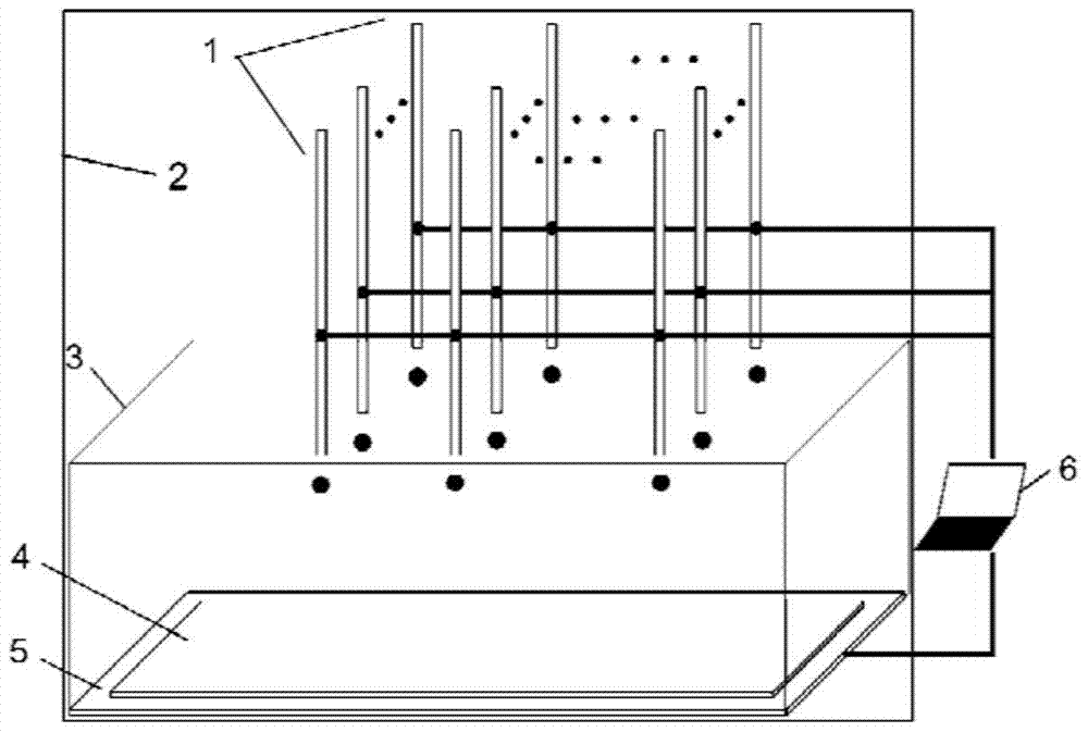
[0060] printing system such as figure 1 As shown, it includes: printing nozzle 1, thermostat 2, bath 3, printing substrate 4, electrode metal plate 5, power supply and motion control module; printing nozzle includes 9 nozzles, arranged in a 3×3 array, printing nozzle 1 and printing The substrates 4 are vertically opposite, and the printed substrate 4 is placed on the electrode metal plate 5 . The printing substrate 4 and the electrode metal plate 5 are in the bath 3 ; In this embodiment, the inner diameter of the print head 1 is 0.51 mm.
[0061] The bath 3 is a cuboid container made of plexiglass with a volume of 10L, and the NaOH solution with a concentration of 0.2mol / L is filled inside. The printing substrate 4 is selected as an aluminum alloy plate, and the material of the electrode metal plate 5 is copper.
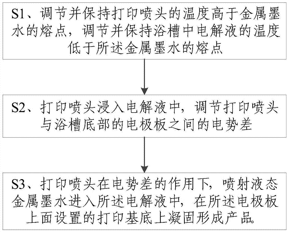
[0062] Select BiSn 40 (The melting point is 138°C) is the printed metal ink. Set the thermostat 2 to 160°C and the t...
Embodiment 2
[0063] Example 2: Printing method of one-dimensional metal rod
[0064] The printing system is as in Example 1.
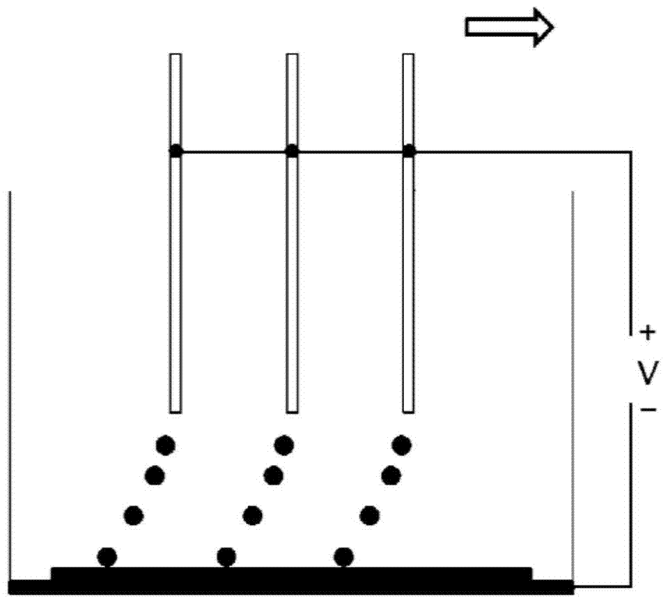
[0065] Metallic ink for printing chooses BiSn 40 (The melting point is 138°C), the incubator is set at 160°C, the bath is set at 80°C, the inner diameter of the print head is 0.51mm, the voltage between the print head and the electrode plate is set at 0.50V, the print head moves vertically upwards and set The speed is 1mm / s. After the droplet falls, it fuses with the deposited metal wire and solidifies rapidly to obtain a thin metal rod. The printing process is as follows: Figure 4 shown.
Embodiment 3
[0066] Embodiment 3: printing method of two-dimensional metal structure
[0067] The printing system is as in Example 1.
[0068] The two-dimensional structure to be printed is a hexagonal star metal surface, choose BiSn 40 (The melting point is 138°C) is the printed metal ink, the thermostat is set to 160°C, the bath is set to 80°C, the inner diameter of the print head is 0.51mm, the voltage between the print head and the electrode plate is set to 0.50V, set the print head The running speed is 1mm / s, and the running path of the nozzle is set in the motion control module, and then the printing is started. Finally, the printed hexagonal star metal plane structure is taken out and surface processed to obtain the finished product. The printing process is as follows: Figure 5 shown.
PUM
| Property | Measurement | Unit |
|---|---|---|
| volume | aaaaa | aaaaa |
| melting point | aaaaa | aaaaa |
| melting point | aaaaa | aaaaa |
Abstract
Description
Claims
Application Information
 - R&D
- Intellectual Property
- Life Sciences
- Materials
- Tech Scout
- Unparalleled Data Quality
- Higher Quality Content
- 60% Fewer Hallucinations
Browse by: Latest US Patents, China's latest patents, Technical Efficacy Thesaurus, Application Domain, Technology Topic, Popular Technical Reports.
© 2025 PatSnap. All rights reserved.Legal|Privacy policy|Modern Slavery Act Transparency Statement|Sitemap|About US| Contact US: help@patsnap.com


