
Wave prevention and elimination device used for harbor basin entrance

A wave-dissipating device and wave-prevention technology, applied in breakwaters, water conservancy projects, marine engineering, etc., can solve the problems of high engineering cost, high design wave height, and difficult engineering site, and achieve longer service life, higher service cycle, and lower cost. Design wave height effect

Inactive Publication Date: 2016-07-27
HOHAI UNIV
View PDF6 Cites 1 Cited by
  • Summary
  • Abstract
  • Description
  • Claims
  • Application Information

AI Technical Summary

Problems solved by technology

However, although the location of the port is designed to avoid the direction of strong waves, the diffraction phenomenon generated during wave propagation cannot be ignored, so there are still wave propagation phenomena in the harbor basin under normal working conditions
Unfavorable wave conditions in the harbor basin will require a higher design wave height for the hydraulic structures inside the harbor basin, which will easily lead to problems such as increased difficulty in engineering construction, high engineering costs, and difficult maintenance and operation of buildings and auxiliary facilities in the later period. Unfavorable wave conditions can also easily have adverse effects on ships berthing
[0003] In related fields related to port hydraulic structures, little attention has been paid to the structural type of wave-proof and wave-dissipating components at the port gate. The design has low hydrophilicity and requires large-scale equipment support to realize it, so it is difficult to apply it to the engineering site

Method used


Image

  • Wave prevention and elimination device used for harbor basin entrance
  • Wave prevention and elimination device used for harbor basin entrance
  • Wave prevention and elimination device used for harbor basin entrance

Examples


Embodiment Construction

[0027] The present invention will be further described below in conjunction with accompanying drawing:

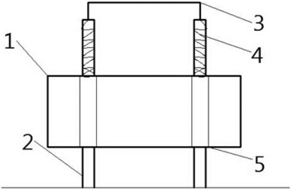
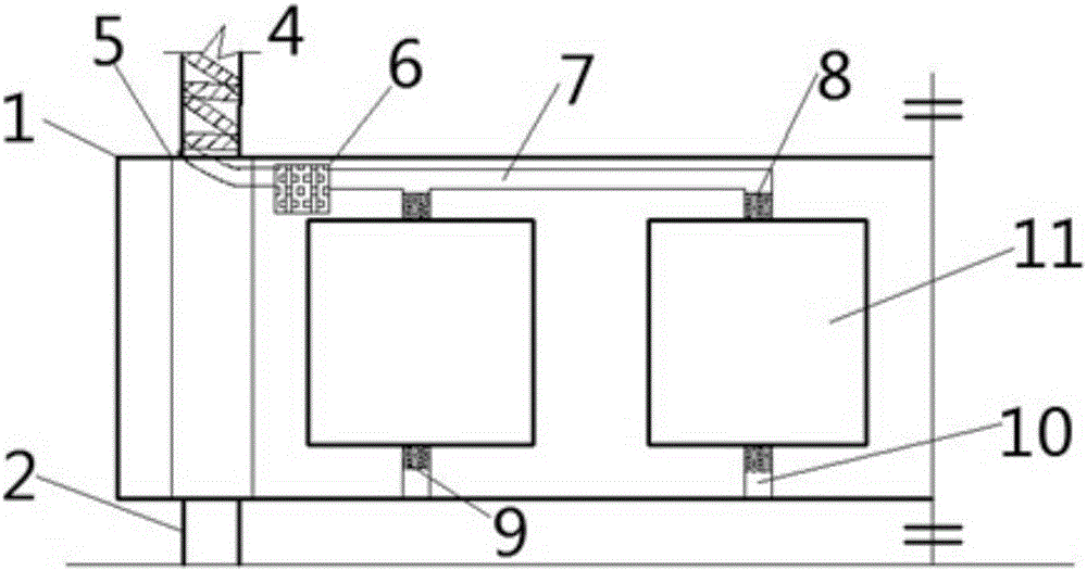
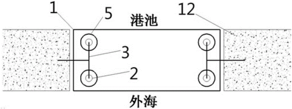
[0028] As shown in the figure, the present invention includes a rectangular buoyancy tank 1, a vertical guide pile 2, a rigid frame 3, a conduction line pipe 4, a limiting plate 5, an air pump 6, an inflation and exhaust valve 8, an inflation and exhaust pipeline 7, a water filling Technical features such as drainage valve 9, water-filled drainage pipe 10, box body 11, breakwater 12, circuit channel 13, air flow channel 14, air flow channel outlet 15 and circuit line 16.

[0029] Such as image 3 As shown, the present invention is overall arranged at the gate formed between the breakwaters as the gate of the harbor basin, the inner side of the overall structure is the harbor basin, and the outer side is the open sea; the vertical guide piles are arranged between the breakwaters on both sides of the harbor basin gate, and the upper ends of the vertical guide piles The lower...


PUM


Abstract

The invention discloses a wave prevention and elimination device used for a harbor basin entrance. The wave prevention and elimination device comprises a sealed rectangular buoyant box. A plurality of vertical guide piles are connected to the rectangular buoyant box in a penetrating mode. One end of each vertical guide pile is vertically piled into the bottom of a harbor basin, and the other end of the vertical guide pile stretches out of the rectangular buoyant box. The exterior of the portion, stretching out of the rectangular buoyant box, of each vertical guide pile is wound by a spiral conducting wire tube. The conducting wire tubes are made of elastic materials. A plurality of box bodies are arranged in the rectangular buoyant box. A inflating and deflating valve is arranged at the upper end of each box body. The inflating and deflating valves are connected to a inflating and deflating pipeline. The inflating and deflating pipeline is connected to an air pump. The air pump is connected outwards to the conducting wire tubes. A water filling and draining valve is connected to the lower end of each box body. The water filling and draining valves are connected to a water filling and draining pipeline. The water filling and draining pipeline is connected outwards to the exterior of the rectangular buoyant box. The wave prevention and elimination device has a wave prevention function at the harbor basin entrance, ships can get in and out of the harbor basin conveniently, the design wave height of relative buildings in the harbor basin is effectively decreased, and ship mooring stability is achieved.

Description

technical field [0001] The invention relates to a wave-preventing and wave-suppressing device for a harbor basin entrance, belonging to the technical field of harbor hydraulic structures. Background technique [0002] The function of the breakwater is to provide good mooring conditions for the port area, block the impact of waves, maintain a stable water surface in the harbor, and facilitate ship loading and unloading operations. A gate is formed between the dikes of the breakwater as a channel for ships to come and go. However, although the location of the port is designed to avoid the direction of strong waves, the diffraction phenomenon generated during wave propagation cannot be ignored, so wave propagation still exists in the harbor basin under normal working conditions. Unfavorable wave conditions in the harbor basin will require a higher design wave height for the hydraulic structures inside the harbor basin, which will easily lead to problems such as increased diffi...

Claims


Application Information

Patent Timeline
Patent Type & Authority Applications(China)
IPC IPC(8): E02B3/06
CPCE02B3/062Y02A10/11
Inventor 冷杰仲轩野吴夏萍罗成李文馨冯辉
Owner HOHAI UNIV
Learn More