Composite tail pier for removing water wings

A composite tail pier and water fin technology, which is applied to the tail pier of the water fin phenomenon behind the gate pier of the flood discharge tunnel or behind the dam pier of the river gate, eliminates the area of ​​the spillway, and can solve the threat to the safe operation of the spillway tunnel, increase the project cost, and affect the construction. Problems such as physical and geological environments can be solved to achieve the effect of optimizing the flow pattern of the discharged water, reducing the pulsating pressure, and saving engineering investment

Active Publication Date: 2016-07-27
SICHUAN UNIV
View PDF4 Cites 2 Cited by
  • Summary
  • Abstract
  • Description
  • Claims
  • Application Information

AI Technical Summary

Problems solved by technology

However, during flood discharge, the phenomenon of water fins (water crowns) is very likely to occur at the tail of the pier. The so-called water fin phenomenon means that when the water flowing from the sluice chamber meets at the tail of the middle pier, a water body similar to the dorsal fin of a fish is stirred up. , this phenomenon often brings many adverse effects and even harms to hydraulic structures
If the discharge water fluctuates slightly or the gates on both sides of the pier are not opened symmetrically, the water fins will swing, impact or even climb over the side walls in the chute, which will inevitably increase the design height of the side walls of the spillway, thereby increasing the project cost
The atomization problem caused by the water mist formed by the strong water fins will also affect the normal operation of electrical equipment in nearby power stations, as well as the surrounding buildings and geological environment.
If the water fins occur in the spillway tunnel, the aroused water flow will easily hit the roof of the spillway tunnel, and the fluctuations caused by it will also cause the water flow in the spillway tunnel to be unstable, seriously threatening the safe operation of the spillway tunnel
In addition, the water fin behind the dam pier of the river gate will also form undesirable flow patterns such as diamond waves, which will interfere with the normal flood discharge and energy dissipation
[0003] The traditional method of reducing the height of the water fin is to add a similar figure 1 The quadrangular pylon-shaped tail pier shown in the figure, although this type of tail pier can reduce the phenomenon of water fins to a certain extent, it still cannot effectively avoid the occurrence of water fins, especially when the discharge flow is large or medium. However, the water fins of the pier will still affect the stability of the discharge flow, so there are still some limitations in the practical engineering application of this type of pier

Method used


Image

  • Composite tail pier for removing water wings
  • Composite tail pier for removing water wings
  • Composite tail pier for removing water wings

Examples


Embodiment 1

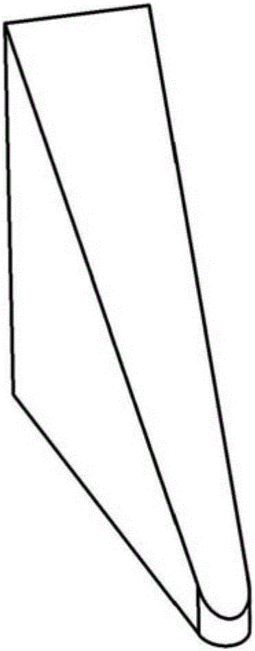
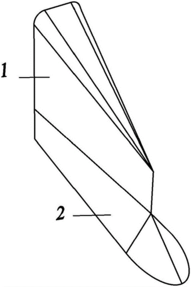
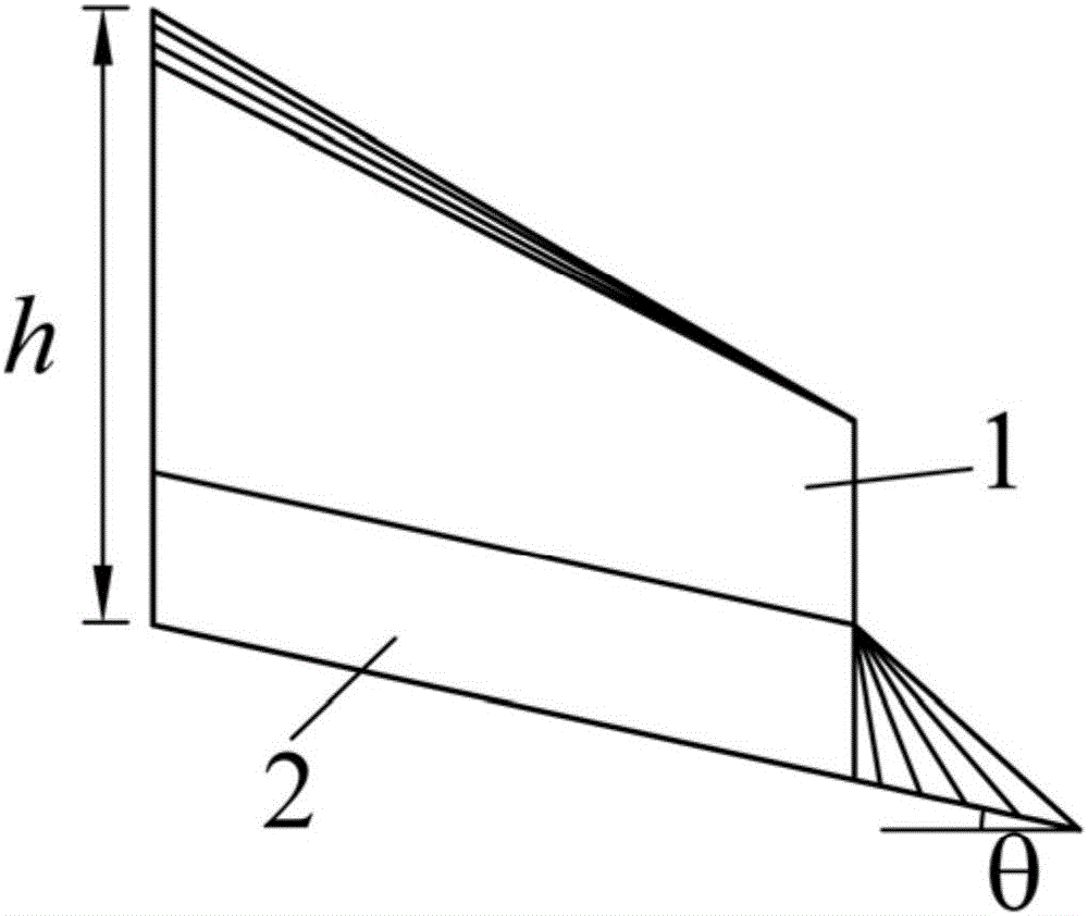
[0038] In this embodiment, the composite tail pier that eliminates water fins is formed by pouring reinforced concrete, and the structural schematic diagram of the composite tail pier is shown in Figure 2-9 shown. The composite tail pier is used behind the gate pier of the spillway inlet. The overflow weir of the project is a practical weir. The width of the gate pier is 4.5m, and the shape of the tail of the gate pier is rectangular. The maximum Froude number Fr of the flow m = 3.2, the maximum water depth at the tail of the gate pier is 11.5m, and the slope angle of the spillway θ = 12.5°.

[0039] In this embodiment, the composite tail pier that eliminates the water fins is composed of the water barrier pier 1 located at the upper part and the supporting flow pier 2 located at the lower part, and the water blocking pier and the supporting flow base are integrated structures;

[0040] The water barrier 1 is a pentahedron with a first rear end surface 1-1, a first left sid...

Embodiment 2

[0045] In this embodiment, the composite tail pier that eliminates water fins is formed by pouring reinforced concrete, and the structural schematic diagram of the composite tail pier is shown in Figure 2-9 shown. The composite tail pier is used behind the river gate pier. The overflow weir of the project adopts a wide top weir and three holes for flood discharge. The width of the gate pier is 5m. The shape of the tail of the gate pier is rectangular. Maximum Froude number Fr of leakage m =2.6, the maximum water depth at the end of the gate pier is 12m.

[0046] In this embodiment, the composite tail pier that eliminates the water fins is composed of the water barrier pier 1 located at the upper part and the supporting flow pier 2 located at the lower part, and the water blocking pier and the supporting flow base are integrated structures;

[0047] The water barrier 1 is a pentahedron with a first rear end surface 1-1, a first left side surface 1-2, a first right side surfa...


PUM


Abstract

The invention provides a composite tail pier for removing water wings. The composite tail pier is composed of a waterproof pier body located on the upper portion and a flow supporting pier seat located on the lower portion; and the waterproof pier body and the flow supporting pier seat are of an integrated structure. The waterproof pier body is a pentahedron composed of a first rear end face, a first left side face, a first right side face, a first top face and a first bottom face; the flow supporting pier seat is a curve body composed of a second front end face, a second rear end face, a second left side face, a second right side face, a second top face and a second bottom face; and the second top face and the first bottom face are located on the same face, and the face is a combination face of the flow supporting pier seat and the waterproof pier body. The composite tail pier can effectively remove the water wing phenomenon at the position behind a gate pier, the flow state inside a spillway or a tunnel spillway or a downstream river channel can be improved, and the safety of running of a release structure is improved.

Description

technical field [0001] The invention belongs to drainage facilities of water conservancy and hydropower projects, in particular to a tail pier used for eliminating the phenomenon of water wings behind the pier of a spillway, a flood discharge tunnel or a pier of a river gate. Background technique [0002] In most water conservancy and hydropower projects, when the design flow is large, gate piers are often added at the inlet section of the spillway to divide the water inlet into several holes to reduce the size of the gate and prevent the gate span from being too large. However, during flood discharge, the phenomenon of water fins (water crowns) is very likely to occur at the tail of the pier. The so-called water fin phenomenon means that when the water flowing from the sluice chamber meets at the tail of the middle pier, a water body similar to the dorsal fin of a fish is stirred up. , this phenomenon often brings many adverse effects and even hazards to hydraulic structure...

Claims


Application Information

Patent Timeline
Patent Type & Authority Applications(China)
IPC IPC(8): E02B8/06
CPCE02B8/06
Inventor 薛宏程刁明军孙浩淼王磊
Owner SICHUAN UNIV
Why Eureka
Try Eureka